8.2. Initialization Pulse Adjust
1. Input a white signal to plasma video input.
Aging pattern : 0
2. Set the picture adjustment items as follows.
·
Picture menu : Standard
·
Color temperature : Normal
·
Picture : 25
·
Aspect : Full
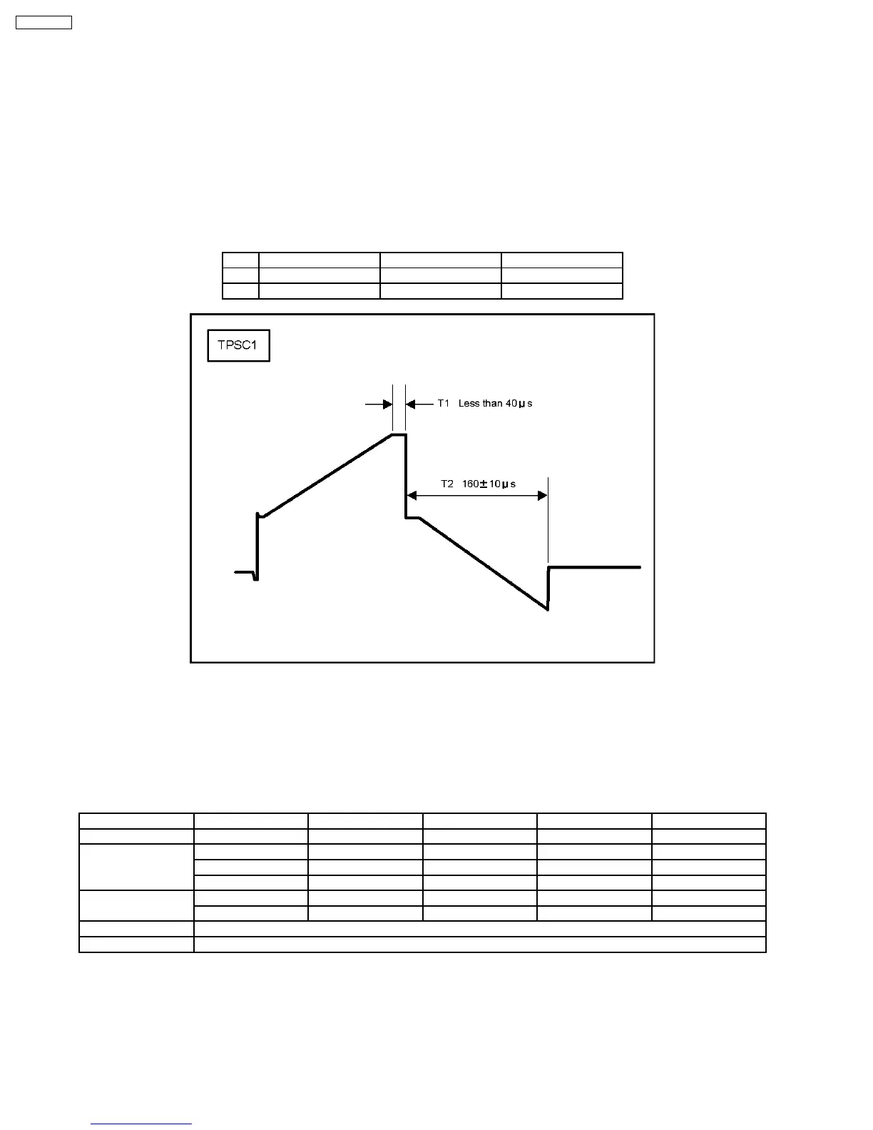
3. Connect Oscilloscope to TPSC1 (T1) and check for less than 40µ Sec.
4. Connect Oscilloscope to TPSC1 (T2) and adjust VR6602 for 155 ± 10µ Sec.
Test point Volume Level
T1 TPSC1 (SC) Fixed Less than 40µ Sec
T2 TPSS1 (SS) VR6602 (SC) 160 ± 10µ Sec
8.3. P.C.B. (Printed Circuit Board) Remove
8.3.1. Caution
1. To remove P.C.B., wait 1 minute after power was off for discharge from electrolysis capacitors.
8.3.2. Quick adjustment after P.C.B. Remove
P.C.B. Name Test Point Voltage Volume Remarks
P Board Vsus TPVSUS Vsus ± 2V VR251 (P) *
SC Board Vad TPVAD -90V ± 1V VR6600 (SC)
Vscn TPVSCN Vad + 140V ± 4V Fixed
Vset TPVSET 240V ± 7V Fixed
SS Board Ve TPVE Ve ± 1V VR6600 (SC) *
Vda TPVDA 72V ± 1V, -3V Fixed
D, DS Board White balance and Sub brightness for NTSC, PAL, HD, PC and 625i signals
DN Board Set Market Select Number to correct destination by Ms mode (See chap. 9.1.4)
*See the Panel label.
Caution:
Absolutely do not reduce Vsus below Ve not to damage the P.C.B.
26
TH-65PF9UK