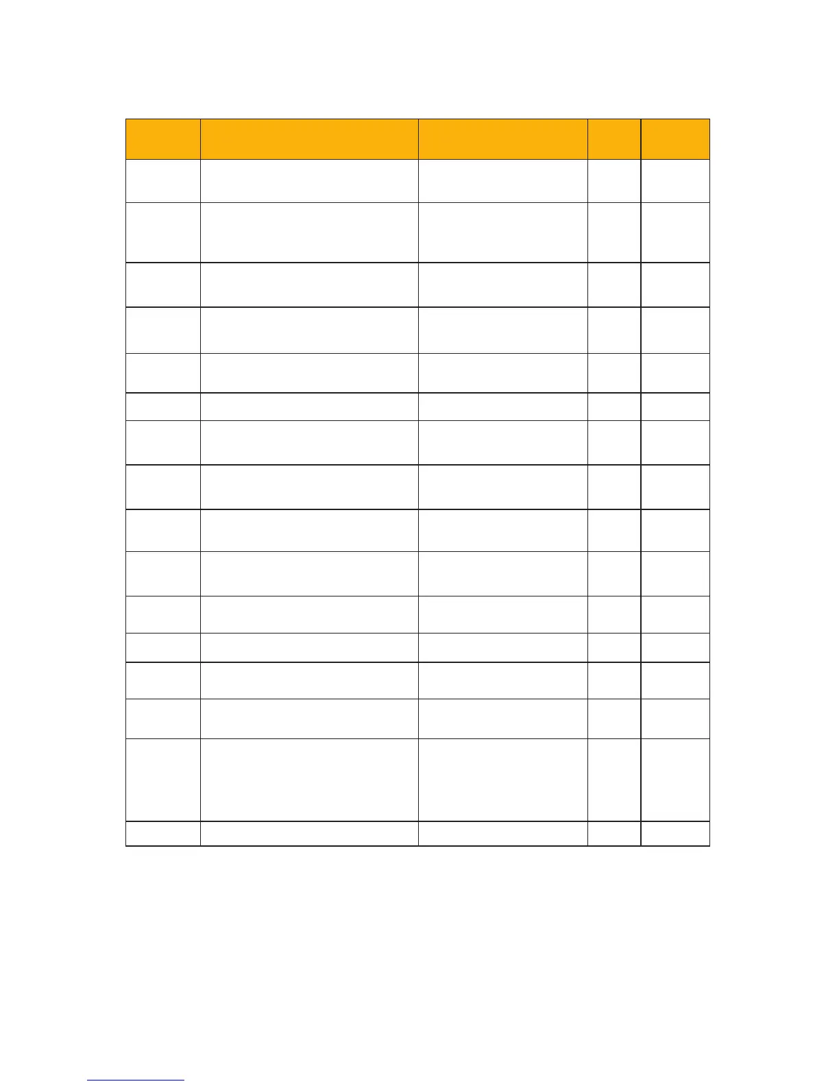
Function
Code
Function Denition Setting Range Value Change
F400
Lower limit of AI1 channel
input
0.00-F402 0.01 √
F401
Corresponding setting for
lower limit of AI1 input
0-F403 1.00 √
F402
Upper limit of AI1 channel
input
F400-10.00 10.00 √
F403
Corresponding setting for
upper limit of AI1 input
Max (1.00, F401) -
2.00
2.00 √
F404
AI1 channel proportional
gain K1
0.0-10.0 1.0 √
F405 AI1 ltering time constant 0.01-10.0 0.10 √
F406
Lower limit of AI2 channel
input
0.00-F408 0.01 √
F407
Corresponding setting for
lower limit of AI2 input
0-F409 1.00 √
F408
Upper limit of AI2 channel
input
F406-10.00 10.00 √
F409
Corresponding setting for
upper limit of AI2 input
Max (1.00, F407) -
2.00
2.00 √
F410
AI2 channel proportional
gain K2
0.0-10.0 1.0 √
F411 AI2 ltering time constant 0.01-10.0 0.10 √
F418
AI1 channel 0Hz voltage
dead zone
0-0.50V (Positive-
Negative)
0.00 √
F419
AI2 channel 0Hz voltage
dead zone
0-0.50V (Positive-
Negative)
0.00 √
F421 Keypad selection
0: Local keypad
1: Remote keypad
2: Local + remote
keypad
1 √
F422 Reserved
Parameter List and Default Settings
10-10

 Loading...


