Page 14 – Bulletin 100-50-9.1
5. COMPONENT MOUNTING AND WIRING
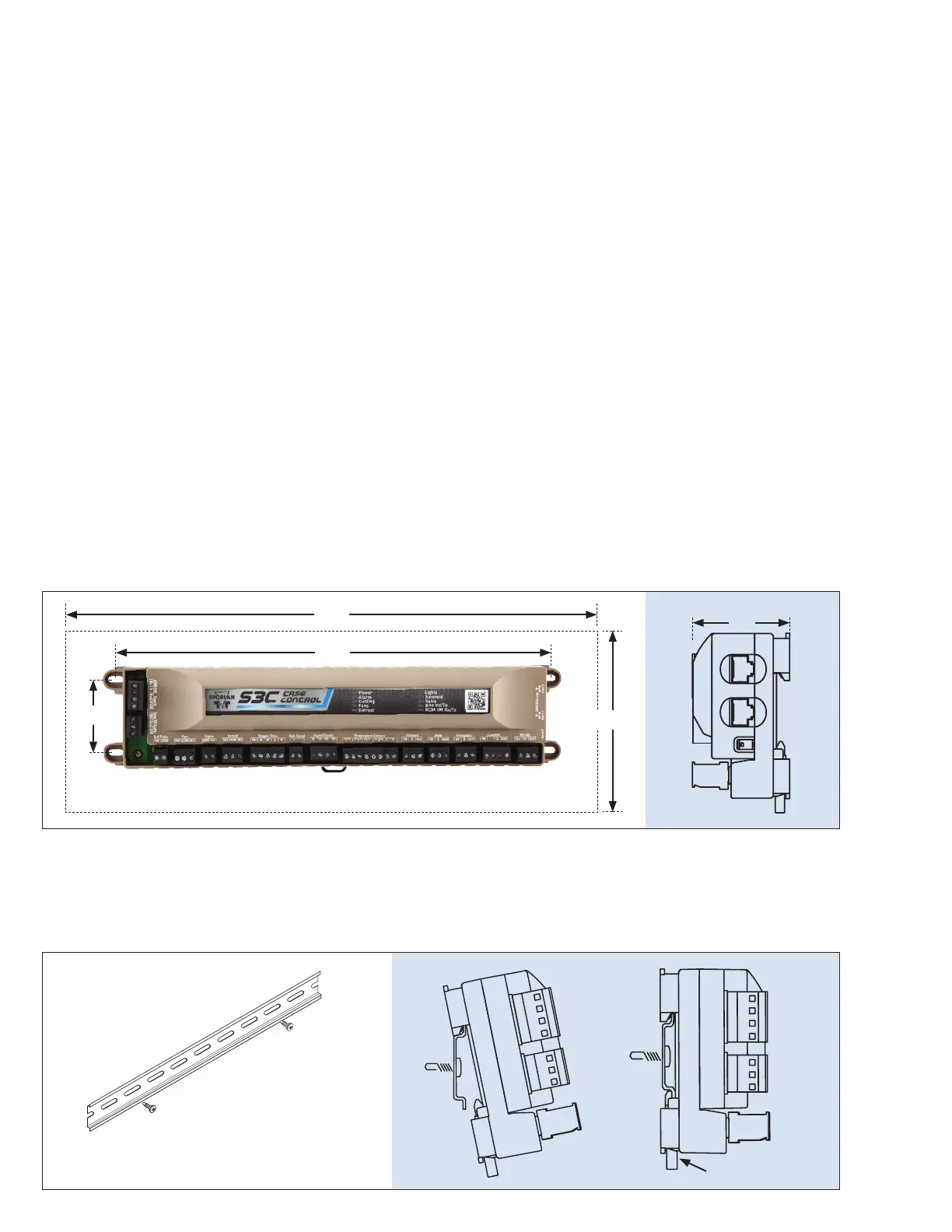
5.1 S3C CASE CONTROL
5.1.1 MOUNTING FLANGE
Mount the controller in a rain-tight protected location using #8 sheet metal screws; tighten to 14-16 in.-lb. The suggested
mounting area is 6 inches high and 16 inches wide, depth is 3 inches.
5.1.2 MOUNTING DIN RAIL
Mount the controller in a rain-tight protected location. Fasten a 14” length of EN 50022 DIN 3 rail (35 mm height X 7.5 mm
depth) to the surface where the controller will be mounted. Place the top of the controller down onto the top of the DIN
Rail. Lower bottom of controller into place until DIN latch catches.
#8 sheet metal screws, 4 places, tighten to 14-16 in.-lb.
13”
16”
2.2”
6”
3”
Take precaution when drilling thru electrical panels,
be aware of what is on the other side of the panel.
DIN Latch
4.16 DIAGNOSTICS
The S3C Case Control system employs sensors and diag-
nostic algorithms to detect and aid in the diagnoses of fault
conditions in the case and in some instances the refrigera-
tion system as a whole. The S3C Case Control system moni-
tors, alarms and provides system diagnostics in two areas:
1. Detect and report problems with sensor inputs and
stepper motor valves.
2. Detect and report problems with case components
such as fans and defrost heaters.
4.17 FAILSAFE OPERATION
The S3C Case Control system relies on inputs from several
external devices to maintain proper control of the case. The
inputs are divided into two types:
1. Hardware inputs
2. Software inputs.
Hardware inputs are physical sensors directly connected
to the case controller. These sensors include temperature
sensors and pressure transducers. Software inputs are pro-
vided via communications link to the BAS or from a peer
case controller.
In the event of a sensor fault the controller will notify the
BAS of the issue and attempt to control the system when
possible. Employing redundant sensors such as pressure
transducers on a common suction line, multiple DA/RA
sensors in a case or line-up allows the system to adapt and
continue to control based on averages of the values reported
by the remaining functional sensors.
If communication to the BAS system is lost, the case control-
ler will continue to operate as a standalone device perform-
ing all required control functions and defrost scheduling in
accordance with its congured operating parameters and
schedules.

 Loading...


