Bulletin 100-50-9.1 – Page 17
5.4 SENSORS
The S3C control system uses input from several sensors
to control case discharge air, superheat and defrost. It is
important to follow these instructions to ensure proper
location and mounting technique. All sensors should be
provided by Sporlan to ensure compatibility and proper
operation.
Note: Sensor leads may be extended to 100 ft. (30.5m)
with 18 AWG wires and Scotchlok
TM
UR connectors for
long-term integrity. For extending the pressure trans-
ducer cable it is recommended to use Belden 9493 or
equivalent. For extending temperature sensor cabling
it is recommended to use Belden 9409 or equivalent.
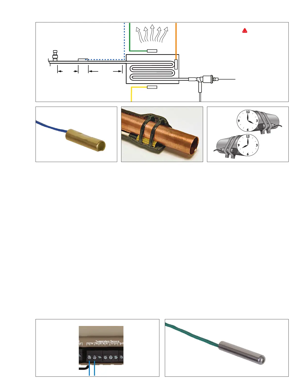
5.4.1 COIL OUTLET TEMPERATURE
5.4.1.1 MOUNTING
The coil outlet temperature sensor is required when using an
EEV and where superheat calculation is needed. The sensor
must be mounted on the suction line after the evaporator as
shown in the figure above. The piping must be horizontal
and free draining. Position the sensor at the 4 or 8 o’clock
position on the suction line. Secure with two heavy duty zip
ties, then insulate.
5.4.1.2 WIRING
With controller unpowered, carefully route the blue coil
outlet sensor leads to the controller. Take caution to route
the leads away from sharp edges, fans and defrost heaters.
Ensure the terminal screws on the controller are backed
all the way out. Insert the leads of the sensor wire into
“Coil Out” location on the controller. Tighten the terminal
screws to 3-5 in.-lb. Carefully tug the leads to ensure they
are secure. See the figure below. Note: Leads are not
polarized and may be installed in either location. One
lead of the coil out sensor will share the terminal with
the discharge air sensor.
5.4.2 DISCHARGE AIR TEMPERATURE
5.4.2.1 MOUNTING
The discharge air temperature sensor is required for case
temperature control. The sensor must be mounted inside of
the refrigerated display case. Typical location is the middle
of the case, inside top. The sensor should be mounted in
the discharge air stream, away from large thermal masses
such as mounting brackets and or case struts. Secure with
two heavy duty zip ties. Note: The controller may be
configured to use the discharge air sensor or return
air sensor as the control point.
Coil Outlet
Sensor
Pressure
Transducer
EEV
10”-14”
minimize
1”- 2”
ideal
Evaporator
Discharge Air Sensor
Defrost
Termination Sensor
Return Air Sensor
WARNING: Route
and secure cables away
from hot surfaces, high
voltage lines and moving
components.

 Loading...


