Page 90 – Bulletin 100-50-9.1
6.22.1 DOOR SWITCH OPERATION
A door switch may be used on low temperature walk-in freezer applications. When the door switch is active, the S3C case
controller will shut off evaporator fans and will turn off refrigeration by closing the liquid line solenoid valve and EEV. Once
activated, the system will remain off for 15 minutes. The door switch polarity may be set through communications.
6.23 CONTROLLER REQUIREMENTS CHART
The following chart shows the required hardware per configuration. Quantities are per case unless otherwise noted.
Configuration Case Controller Display Module Valve Module
A 1 1
B 1 1
C 1 1 1
D 1 1 1
E 1 1
F 1 1
G 1 1
H 1 1
I 1 1 1 (per line-up)
J 1 1 1
K 1 1 1
L 1 1 1
M 1 1
N 1 1 1
O 1 1 2 (1 per case, 1 per line-up)
P 1 1 1
Q 1 1 2
R 1 1
S 1 1 1 (per line-up)
T 1 1 1
U 1 1
V 1 1 1
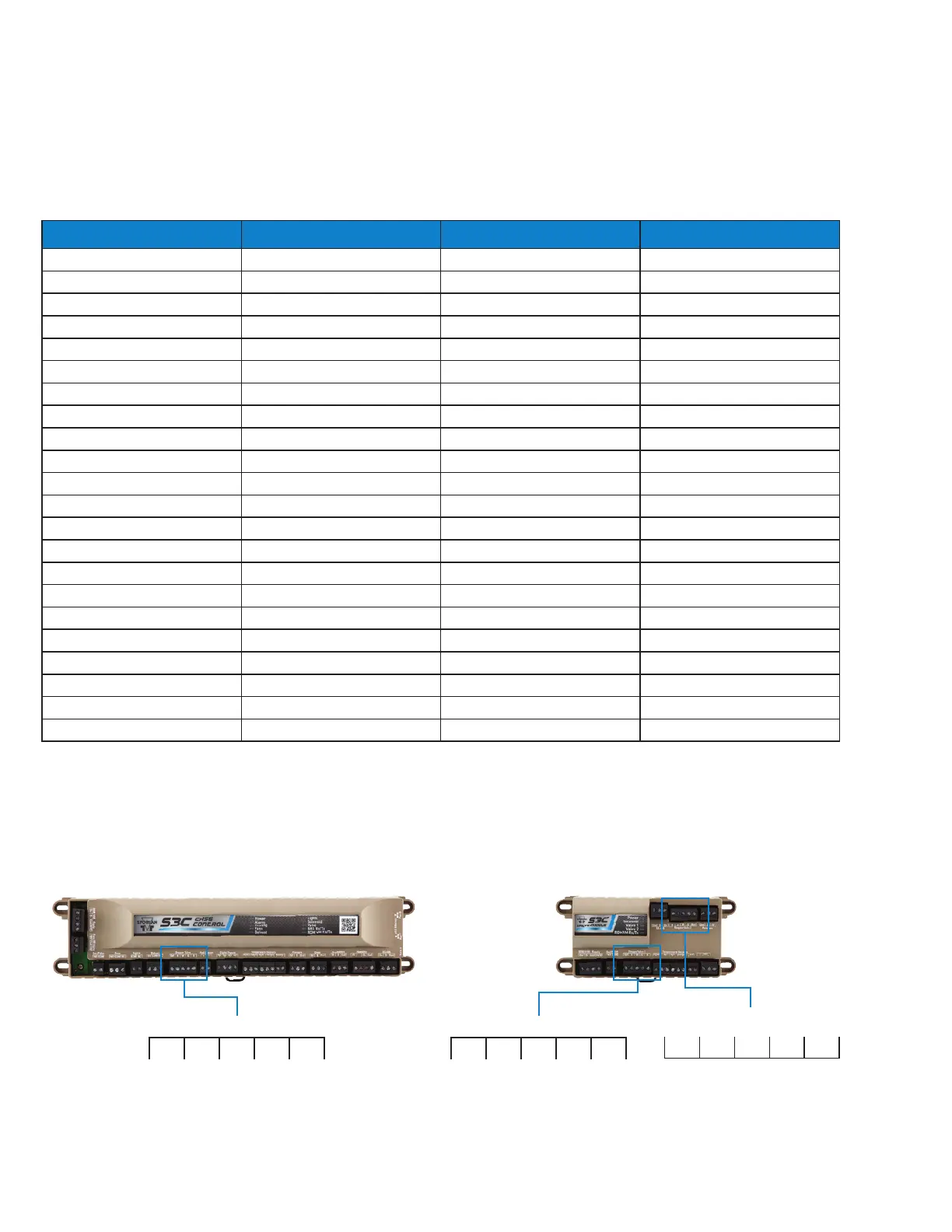
6.24 VALVE WIRING LOCATION CHART
The below chart shows valve wiring location based on the controller input. For example: Valve Module 2, “Stepper Valve
2” indicates that the valve is located on a second Valve Module and wired into the “Stepper Valve 2” location on that
controller. See following figure for wiring location.
S3C CASE CONTROLLER S3C VALVE MODULE
Stepper Valve
Ref B W G R
Stepper Valve 1
Ref B W G R
R G W B Ref
Stepper Valve 2

 Loading...


