Connect a DSO with 50 inputs to the
BNC connectors, one at time.
Verify that the four output signals are
sinusoidal and that the voltage is >1Vp-p,
typically 1Vrms.
Connect the timer/counter and verify that
the frequency is 10MHz ± 0.01Hz,
5MHz ± 0.005Hz, 1MHz ± 0.001Hz and
0.0MHz ± 0.0001Hz respectively.
– Connect a 10 MHz sine wave signal with
approx. 1 V
RMS
amplitude into 50 Ωvia a
power splitter to Input A and Input B, e.g
from 10 MHz Out on the rear panel.
– Recall the DEFAULT settings.
Select the following settings for
timer/counter via INPUT A and INPUT B:
Check that the timer/counter performs the
correct measurement by displaying the
results shown in the “Display” column of
Table 7-7.
Select function via MEAS FUNC.
Note that the results are rounded off and
very approximate. No tolerances are
given for this test.
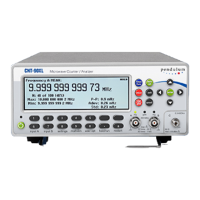
The CNT-90 and the CNT-91 with
optional RF inputs as well as the
CNT-90XL with its various microwave
converters all require an external RF
source to verify Input C. A simple
functional check can be performed by
connecting a 1 GHz, -10 dBm signal after
selecting Freq C. No other settings need
Read 1 GHz on the display and for the
CNT-90XL also the input power level
(about -10 dBm).
– Recall the DEFAULT settings.
– Select Period Single A.
Select the following common timer/counter
settings for both Input A and Input B via the
hard menu keys INPUT A and INPUT B:
MANual trigger, x1 attenuation.
Press SETTINGS and activate Hold Off.
Select Hold Off On and set the Trigger
Hold Off time to the minimum value
20 ns.
Connect the rear panel output marked
10 MHz OUT to Input A.
Increase the Trigger Hold Off time in
steps by means of the UP cursor key and
note the results:
If Trigger Hold Off time <100 ns the result is
about 100 ns, i.e. the same value as without
Hold Off.
If Trigger Hold Off time >100 ns the result is
about 100 ns + Trig Hold Off time.
Connect the signal to Input B, select
Period Single B and repeat the tests
above.
USER MANUAL ● CNT 9x Series ● Rev.22 February 2020

 Loading...