The total measurement time will be
doubled compared to a single
measurement, because "Duty"
requires 2 measurement steps.
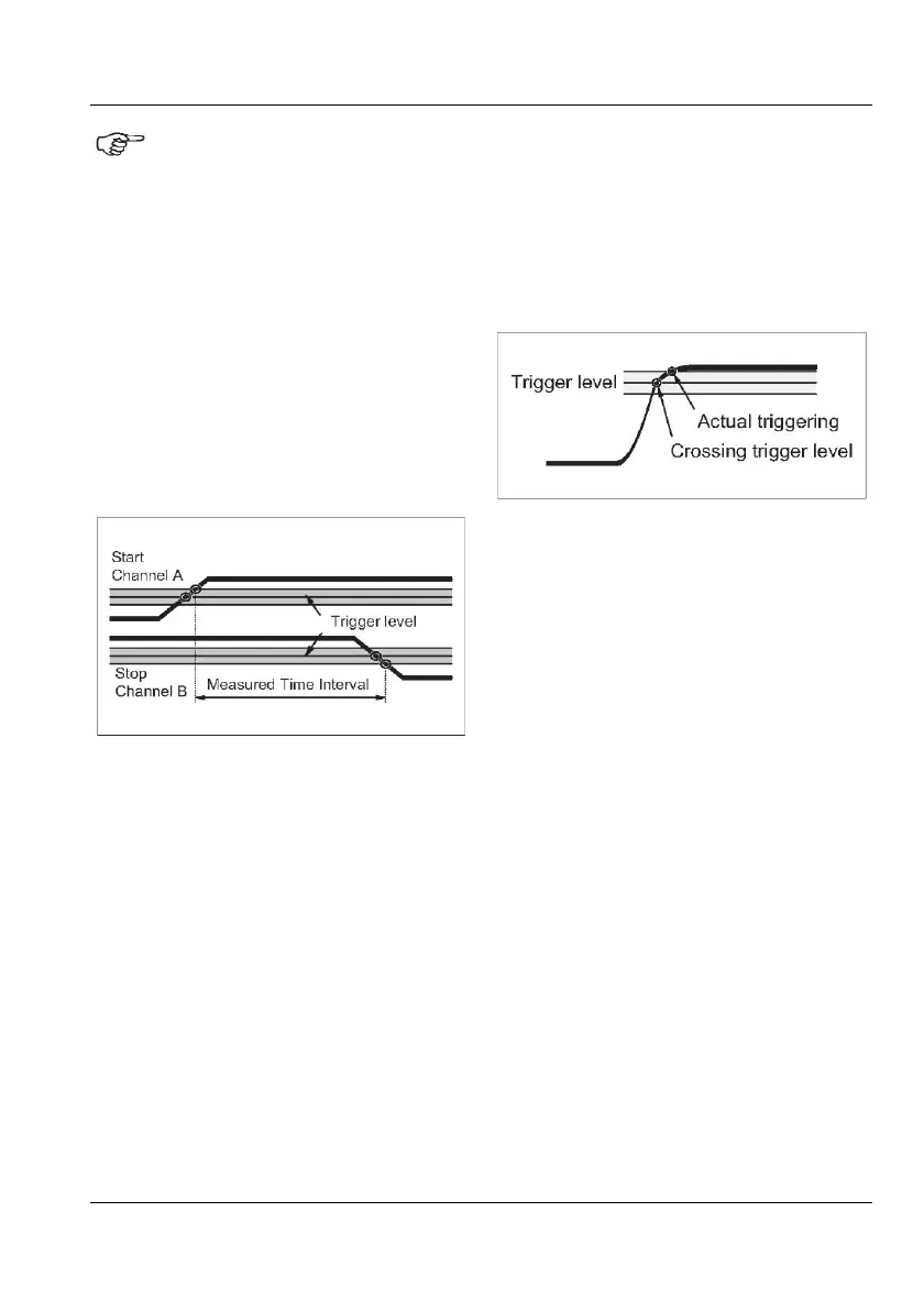
Hysteresis
The trigger hysteresis, among other things,
causes measuring errors, see Figure 4-17. Ac-
tual triggering does not occur when the input
signal crosses the trigger level at 50 percent of
the amplitude, but when the input signal has
crossed the entire hysteresis band.
The hysteresis band is about 20 mV with at-
tenuation 1x, and 200 mV with attenuation
10x.
To keep this hysteresis trigger error low, the
attenuator setting should be 1x when possible.
Use the
10x position only when input signals
have excessively large amplitudes, or when
you need to set trigger levels higher than 5 V.
Rounding
Additional timing errors may be caused by
triggering with insufficient overdrive, see Fig-
ure 4-18. When triggering occurs too close to
the maximum voltage of a pulse, two phenom-
ena may influence your measurement uncer-
tainty: overdrive and rounding.
Insufficient overdrive causes
Trigger Error.
Overdrive: When the input signal crosses the
hysteresis band with only a marginal
overdrive, triggering may take some
100 ps longer than usual. The specified
worst case 500 ps systematic trigger
error includes this error, but you can
avoid it by having adequate overdrive.
Rounding: Very fast pulses may suffer from
pulse rounding, overshoot, or other
aberrations. Pulse rounding can cause
significant trigger errors, particularly
when measuring on
fast circuitry.
USER MANUAL ● CNT 9x Series ● Rev.22 February 2020
4-18