EasyManuals Logo

Pendulum CNT-90 Series User Manual

Pendulum CNT-90 Series
189 pages
To Next Page IconTo Next Page
To Previous Page IconTo Previous Page
Page #25 background imageLoading...
Page #25 background image
Using the Controls
Rear Panel
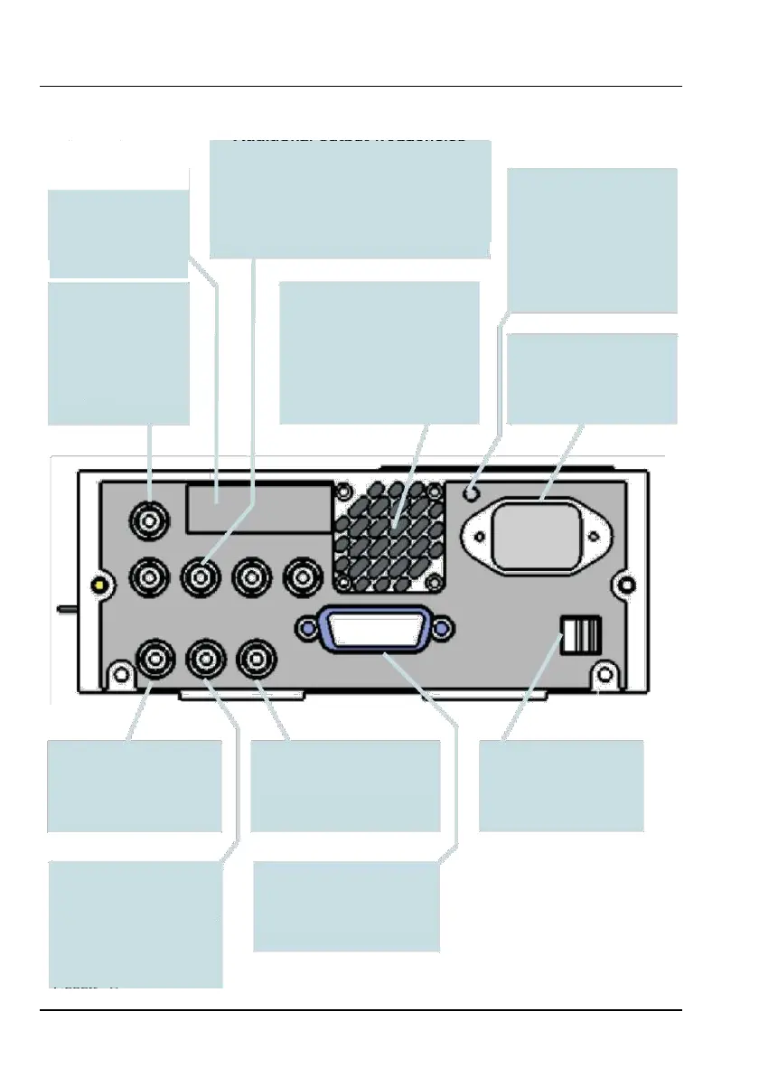
Additional output frequencies
(CNT-91R/71B)
Type Plate
Indicates instrument
type and serial
number.
Connectors
These connectors provide additional output
frequencies which are, from left to right, 100kHz,
1MHz, 5MHz and 10MHz.
Protective Ground
Terminal
This is where the protective
ground wire is connected
inside the instrument. Never
tamper with this screw!
Pulse Output
Fan
User definable to serve
A temp. sensor controls the speed
as output for built-in
of the fan. Normal bench-top use
pulse generator, gate
indicator or alarm.
means low speed, whereas
rack-mounting and/or options may
Line Power Inlet
AC 90-265 VRMS, 45-440
result in higher speed.
Hz, no range switching
needed.
Reference Output
External Arming Input
USB Connector
10 MHz derived from the
internal or, if present, the
See page 5-7.
Universal Serial Bus (USB)
for data communication with
external reference.
PC.
External Reference
GPIB Connector
Input
Address set via User Options
Can be automatically
Menu.
selected if a signal is present
and approved as timebase
source, see Chapter 9.
USER MANUAL CNT 9x Series ● Rev.22 February 2020
2-6

Table of Contents

Other manuals for Pendulum CNT-90 Series

Questions and Answers:

Question and Answer IconNeed help?

Do you have a question about the Pendulum CNT-90 Series and is the answer not in the manual?

Pendulum CNT-90 Series Specifications

General IconGeneral
BrandPendulum
ModelCNT-90 Series
CategoryMeasuring Instruments
LanguageEnglish

Related product manuals