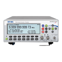
In addition to the traditional measurement
functions of a timer/counter, these
instruments have a multitude of other
functions such as phase, duty factor,
rise/fall-time and peak voltage. The counter
can perform all measurement functions on
both main inputs (A & B). Most measurement
functions can be armed, either via one of the
main inputs or via a separate arming channel
(E).
By using the built-in mathematics and statis-
tics functions, the instrument can process the
measurement results on your benchtop, with-
out the need for a controller. Math functions
include inversion, scaling and offset.
Statistics functions include Max, Min and
Mean as well as Standard and Allan
Deviation on sample sizes up to 2*10
9
.
You will soon find that your instrument is
more or less self-explanatory with an intuitive
user interface. A menu tree with few levels
makes the timer/counter easy to operate. The
large backlit graphic LCD is the center of in-
formation and can show you several signal
parameters at the same time as well as setting
status and operator messages.
Statistics based on measurement samples can
easily be presented as histograms or trend
plots in addition to standard numerical mea-
surement results like max, min, mean and
standard dev
iation.
The AUTO function triggers automatically on
any input waveform. A bus-learn mode sim-
plifies GPIB programming. With bus-learn
mode, manual counter settings can be trans-
ferred to the controller for later
reprogramming. Th
ere is no need to learn
code and syntax for each individual counter
setting if you are an occasional GPIB bus
user.
State of the Art Technology
Gives Durable Use
These counters are designed for quality and
durability. The design is highly integrated.
The digital counting circuitry consists of just
one custom-developed FPGA and a 32-bit
microcontroller. The high integration and low
component count reduces power
consumption and results in an MTBF of
30,000 hours. Modern surface-mount
technology ensures high production quality.
A rugged mechanical construction, including
a metal cabinet that withstands mechanical
shocks and protects against EMI, is also a
valuable feature.
The use of reciprocal interpolating counting
in this new counter results in excellent
relative resolution: 12 digits/s for all
frequencies.
The measurement is synchronized with the
input cycles instead of the timebase. Simulta-
neously with the normal "digital" counting,
the counter makes analog measurements of
the time between the start/stop trigger events
and the next following clock pulse. This is
done in four identical circuits by charging an
integrating capacitor with a constant current,
starting at the trigger event. Charging is
stopped at the leading edge of the first
following clock pulse.
The stored charge in
the integrating capacitor represents the time
difference between the start trigger event and
the leading edge of the first following clock
pulse. A similar charge integration is made
for the stop trigger event.
USER MANUAL ● CNT 9x Series ● Rev.22 February 2020

 Loading...