EasyManuals Logo

Pendulum CNT-90 Series User Manual

Pendulum CNT-90 Series
189 pages
To Next Page IconTo Next Page
To Previous Page IconTo Previous Page
Page #42 background imageLoading...
Page #42 background image
Input Signaling Conditioning
Input Amplifier
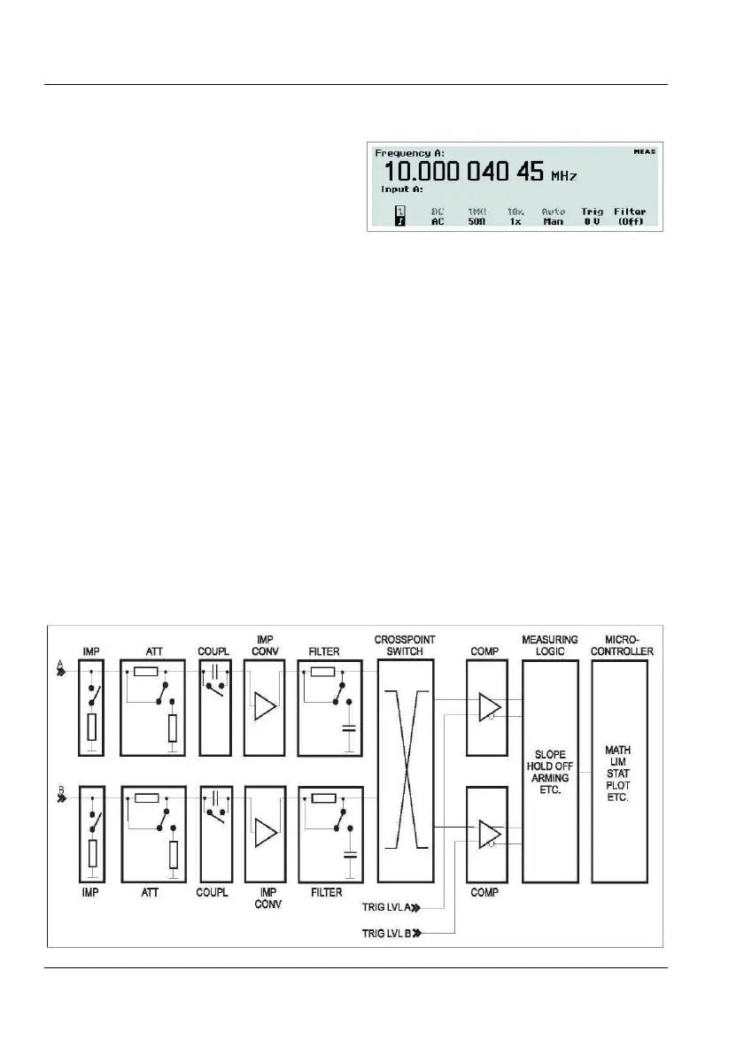
The input amplifiers are used for adapting
the widely varying signals in the ambient
world to the measuring logic of the
timer/counter.
These amplifiers have many controls, and it
is essential to understand how these
controls work together and affect the signal.
The block diagram below shows the order in
which the different controls are connected.
It is not a complete technical diagram but
in- tended to help understanding the
controls.
The menus from which you can adjust the
settings for th
e two main measurement
channels are reached by pressing
INPUT A
respectively INPUT B. See Figure 3-2. The
active choices are shown in boldface on
the bottom line.
Fig. 3-2
Input settings menu.
Impedance
The input impedance can be set to 1 M or 50
by toggling the corresponding softkey.
CAUTION: Switching the impedance to 50
when the input voltage is above 12 VRMS
may cause permanent damage to the input
circuitry.
Attenuation
The input signal's amplitude can be attenuated
by 1 or 10 by toggling the softkey marked
1x/10x.
Use attenuation whenever the input signal ex-
ceeds the dynamic input voltage range ±5 V or
Fig. 3-1
Block diagram of the signal conditioning.
USER MANUAL ● CNT 9x Series ● Rev.22 February 2020
3-2

Table of Contents

Other manuals for Pendulum CNT-90 Series

Questions and Answers:

Question and Answer IconNeed help?

Do you have a question about the Pendulum CNT-90 Series and is the answer not in the manual?

Pendulum CNT-90 Series Specifications

General IconGeneral
BrandPendulum
ModelCNT-90 Series
CategoryMeasuring Instruments
LanguageEnglish

Related product manuals