EasyManuals Logo

Pendulum CNT-90 Series User Manual

Pendulum CNT-90 Series
189 pages
To Next Page IconTo Next Page
To Previous Page IconTo Previous Page
Page #112 background imageLoading...
Page #112 background image
Performance Check
EXT ARM IN
Selected
Function
Action
Display
P/F
RECALL DEFAULT
2)
FREQ A
10 MHz (10 dec.)
FREQ B
10 MHz (10 dec.)
FREQ RATIO
A/B
1 (4 dec.)
FREQ RATIO
B/A
1 (4 dec.)
FREQ BtB A
1)
10 MHz (9 dec.)
FREQ BtB B
1)
10 MHz (9 dec.)
FREQ BURST A
10 MHz (6 dec.)
FREQ BURST B
10 MHz (6 dec.)
PER SINGLE A
100 ns (2 dec.)
PER SINGLE B
100 ns (2 dec.)
PER SINGLE
BtB A
1)
100 ns (6 dec.)
PER SINGLE
BtB B
1)
100 ns (6 dec.)
PER AVERAGE
A
100 ns (9 dec.)
PER AVERAGE
B
100 ns (9 dec.)
TIME INT A - B
0 ns (2 dec.)
TIME INT A - A
0 ns (2 dec.)
TIME INT B - A
0 ns (2 dec.)
TIME INT B - B
0 ns (2 dec.)
SLOPE B
TIME INT A - B
50 ns (2 dec.)
RISE TIME A
30 ns (2 dec.)
RISE TIME B
30 ns (2 dec.)
FALL TIME A
30 ns (2 dec.)
FALL TIME B
30 ns (2 dec.)
TIE A
1)
0 ns (2 dec.)
TIE B
1)
0 ns (2 dec.)
PULSE W POS A
50 ns (2 dec.)
PULSE W NEG A
50 ns (2 dec.)
PULSE W POS B
50 ns (2 dec.)
PULSE W NEG B
50 ns (2 dec.)
DUTY POS A
0.5 (3 dec.)
DUTY NEG A
0.5 (3 dec.)
DUTY POS B
0.5 (3 dec.)
DUTY NEG B
0.5 (3 dec.)
RECALL DEFAULT
PHASE A rel A
(360°)
PHASE A rel B
(360°)
PHASE B rel A
(360°)
PHASE B rel B
(360°)
TOT A
incrementing
TOT B
incrementing
TOT A+B
incrementing
TOT A-B
0
TOT A/B
1.000...
VOLT P-P A
1.5 (3 dec.)
VOLT MAX A
750 mV
VOLT MIN A
-750 mV
VOLT P-P B
1.5 (3 dec.)
VOLT MAX B
750 mV
VOLT MIN B
-750 mV
Proceed from the test above.
Select MANual trigger.
Settings for the pulse generator:
single shot pulse, manual trigger,
amplitude TTL = 0 - 2 V
PP
, and
duration = 10 ns.
Connect the pulse generator to Ext Arm
Input.
Activate start arming by keying in the
following sequence:
SETTINGS
Start Chan E
The counter does not measure.
Apply one single pulse to Ext Arm Input.
The counter measures once and shows
10 MHz on the display.
PULSE OUT (CNT-91 only)
Connect an oscilloscope to the pulse
output on the rear panel with a 50
coaxial cable terminated at the scope
input with 50
(internally or externally).
Select the pulse output by keying in the
following sequence: USER OPT
Output Output Mode Puls Gen
Select Pulse Period and set the value to
1000 ns.
Select Pulse Width and set the value to
500 ns.
The output signal should be a pure square
wave signal with 1 MHz frequency and
50 % duty cycle. The rise/fall time should
be approximately 2 ns. The low and the
high level should be <0.2 V resp. >2.4 V.
Table 7-7
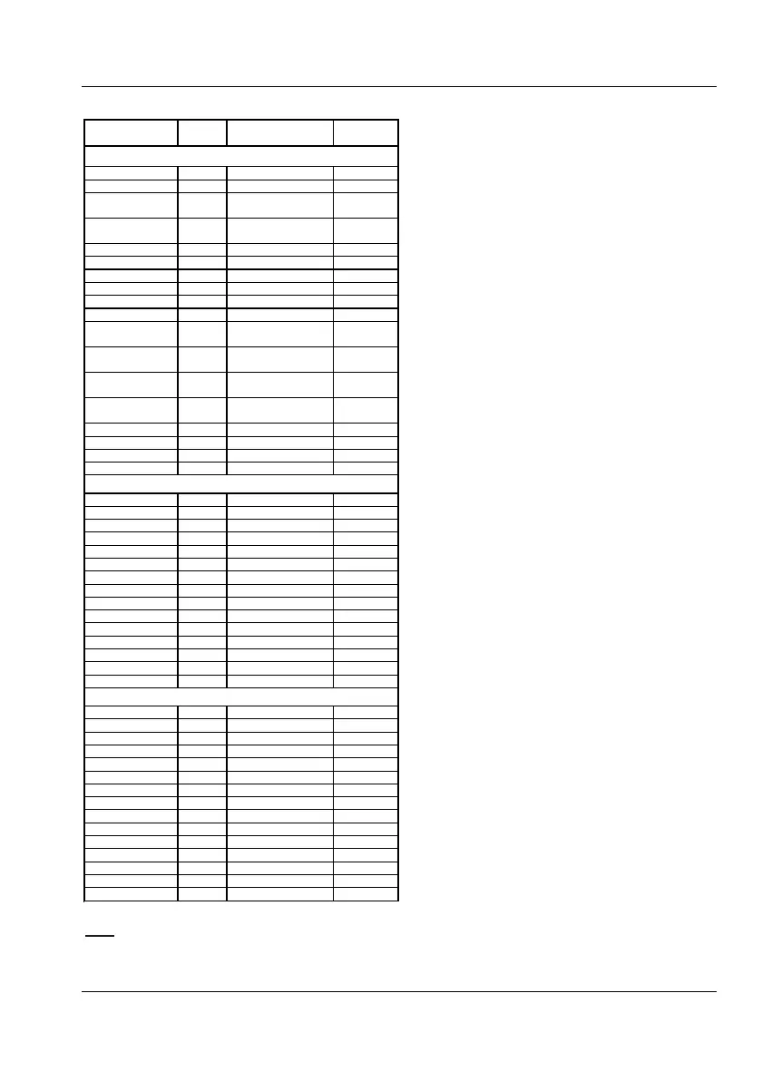
Measuring functions check
Notes: 1) Applies to CNT-91 only; 2) Change default set tings
according to “Measuring Functions” below.
USER MANUAL ● CNT 9x Series ● Rev.22 February 2020
7-10

Table of Contents

Other manuals for Pendulum CNT-90 Series

Questions and Answers:

Question and Answer IconNeed help?

Do you have a question about the Pendulum CNT-90 Series and is the answer not in the manual?

Pendulum CNT-90 Series Specifications

General IconGeneral
BrandPendulum
ModelCNT-90 Series
CategoryMeasuring Instruments
LanguageEnglish

Related product manuals