7-17
USER MANUAL ● CNT 9x Series ● Rev.22 February 2020
Performance Check
1
. Set u
p t
he RF
generator
to 1 GHz
and -10 dB
2.
Set u
p t
he CNT
-90XL counter
for Freq CW measurements:
“Meas Func => Frequency => Freq => C”
still using manual acquisition.
3. Measure the CW mean frequency at 200 msec measuring time with N=10 samples. Note the value as
the reference value F1 in table 3 below
4. Measure the CW mean frequency with a measuring time equal to 90% of the actual pulse width minus
40 ns. E.g. if the pulsed signal has 500 ns wide pulses, this CW measurement should be measured
with 410 ns measuring time.
Use STAT mode with N = 100 000 samples.
Repeat the measurement for PW= 100ns, 500 ns, 1 µs and 10 µs
5. Note the value as the “short gate” value F2 in table 3 below.
The difference F2-F1 is the systematic CW error for a short pulse.
6. Enable Math and enter this value -(F2-F1)
as the Math constant
L in the counter’s Math settings and
select “K*X+L”.
“Math/Limit => Math => K*X+L”, set L = -(F2-F1)
7. Perform the final pulsed RF frequency measurement
“Meas Func => Pulsed RF => Freq in Pulse => C”
with N=100 000 samples and a compensated systematic error (via Math K*X+L) to get a reading
with minimum systematic error
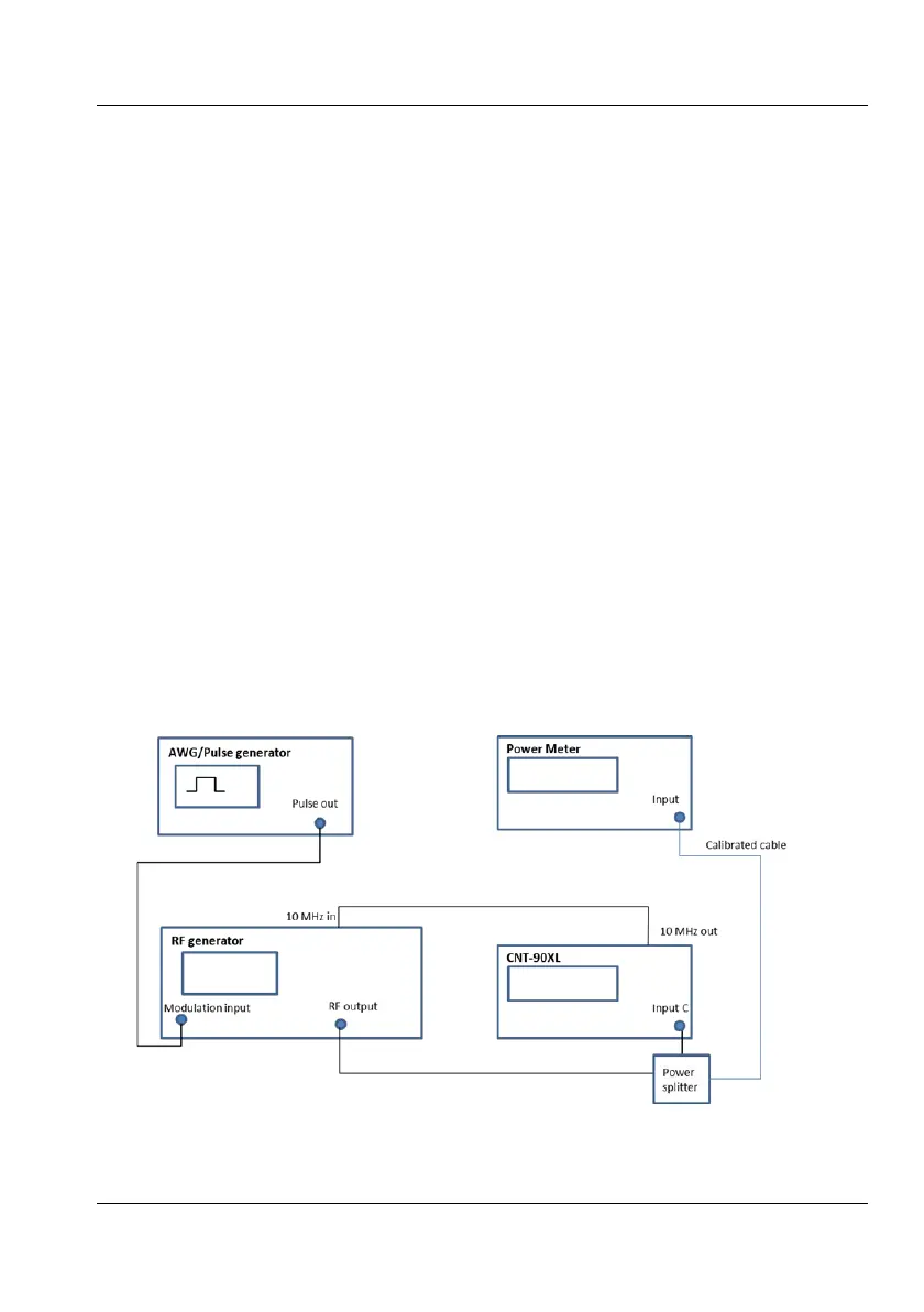
Fig. 7-3. Setup for verifying Pulsed RF parameters