and calculate the mean value from a number
■ Systematic Errors in Phase
Measurements
Systematic errors consist o f 3 elements:
— Trigger level timing errors (start and
stop), due to trigger level uncertainty.
The inter-channel propagation delay differ-
ence is typically 500 ps at identical trigger
conditions in both input channels. Therefore,
the corresponding Phase difference is:
Phase difference caused by
inter-channel propagation delay difference
Trigger level timing error
The "trigger level timing error" is depending
on two factors:
— The actual trigger point is not exactly
zero, due to trigger level DAC uncertainty
and comparator offset error.
— The two signals have different slew rates
at the zero-crossing.
Every counter has input hysteresis. This is
necessary to prevent noise to cause erroneous
input triggering. The width of the hysteresis
band determines the maximum sensitivity of
the counter. It is approximately 30 mV, so
when you set a trigger level of 0 V, the actual
trigger point would normally be +15 mV and
the recovery point -15 mV. This kind of tim-
ing error is cancelled out by using hysteresis
compensation.
Hysteresis compensation means that the mi-
crocomputer can offset the trigger level so
that actu
al triggering (after offset) equals the
set trigger level (before offset). This general
hysteresis compensation is active in phase as
well as in time interval and rise/fall time
measurements. There is a certain residual
uncertainty of a few mV and there is also a
certain temperature drift of the trigger point.
The nominal trigger point is 0 V with a
n un-
certainty of ± 10 mV.
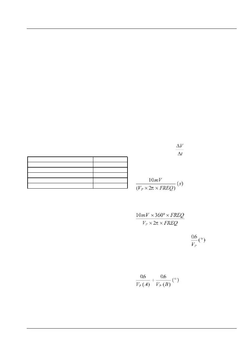
A sine wave expressed as V(t) = V
P
x sin (2π
the zero-crosssing. That gives us the
systematic time error when crossing 10 mV,
instead of crossing 0 mV.
And the corresponding phase error in
This error can occur on both inputs, so the
worst case systematic error is thus:
USER MANUAL ● CNT 9x Series ● Rev.22 February 2020