Using arming as an external Hold
Off.
Input E is the normal arming input. It is
suitable for arming (sync) signals that have
TTL levels. The trigger level is fixed at
1.4V and cannot be changed. The trigger
slope can be set to positive or negative.
The Input E connector can be found on the
rear panel of the instrument.
Input A or Input B can also be used as
arming input for all single channel mea-
surements and dual channel measuremen
ts
where the arming signal is one of the mea-
s
uring signals. This input is more suitab
le
if your arming signal does not have TTL
levels. All input controls such as AC/DC,
Trigger Level, 50
/ 1 M
etc. can be
used to condition the arming signal.
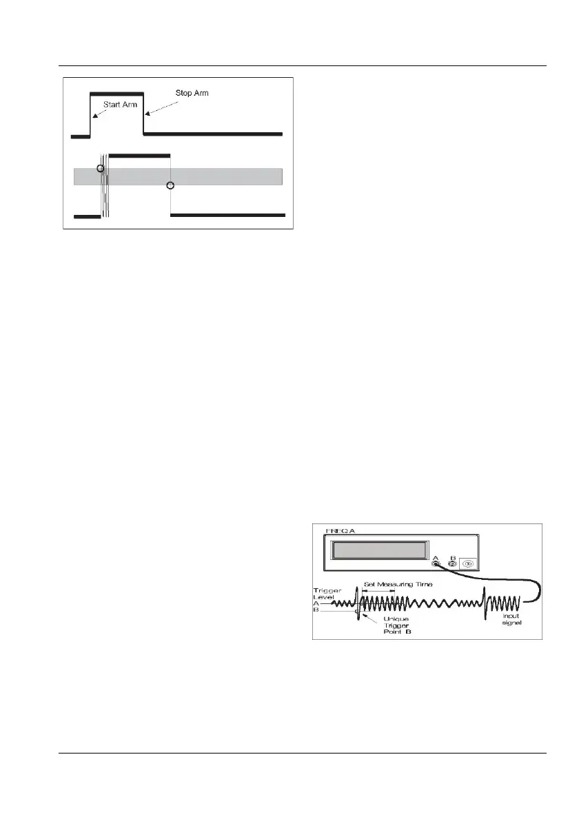
Using the measuring signal as arming
signal
When performing time or frequency measure-
ments on complex signals having a unique
trigger point, input B arming can be used to
make the measuring signal itself "auto-arm"
the counter, e.g. to measure the frequency of a
signal after it has reached a specified voltage
limit (= set trigger level), see Fig. 5-4.
— Connect the signal to input A.
— Press
INPUT A and adjust the settings to
suit the interesting part of the signal.
— Press INPUT B and adjust the settings so
that the unique trigger point can be de-
tected. Normally
DC coupling and Manual
trigger level should be preferred.
— Activate start arming with or without delay
on input B via the
SETTINGS menu.
The signal on input A will be internally con-
nected to input B, so no external signal tap is
necessa
ry.
■ When Do I Use Arming With Delay?
You can delay the start arming point with re-
spect to the arming signal. Use this function
when the external arming signal does not co-
incide with the part of the signal that you are
interested in.
The time delay range is 20 ns to 2 s with a set-
ting resolution of 10 ns.
■ Getting The Whole Picture
The flowchart in Fig. 5-5 illustrates how arm-
ing a trigger hold off enables precise control of
the start and stop of the actual measurement
when you operate the counter from the front
panel. If you control the counter via the GPIB
or USB, read more about bus arming and trig-
gering under the heading "How to use the trig-
ger system" in the Programmer's Handbook.
Auto-arming using the trigger level
on B as qualifier.
5-5
USER MANUAL ● CNT 9x Series ● Rev.22 February 2020