OPC / OPD / OPE
Product Description
2015-07
13
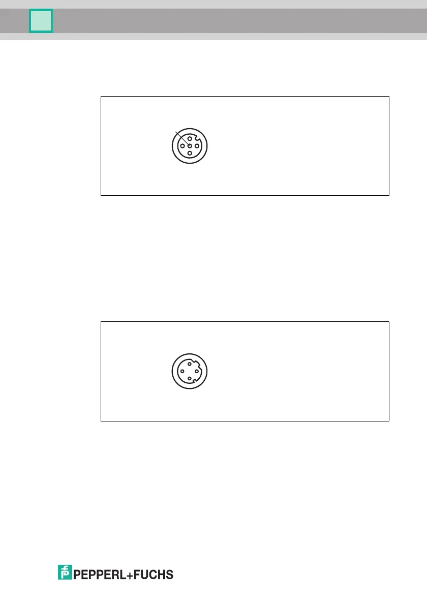
RS-232 Interface
There is a 5-pin M12 socket on the side of the sensor housing. The following
diagram shows the pinning:
Figure 4.4 RS-232 input connection layout
1. + UB
2. TX RS-232
3. GND
4. RX RS-232
5. NC
Network
There is a 4-pin M12 socket on the side of the housing for connecting to the
network. The following diagram shows the pinning:
Figure 4.5 Network connection layout
1. TX+ Ethernet
2. RX+ Ethernet
3. TX- Ethernet
4. RX- Ethernet