2015-07
14
OPC / OPD / OPE
Product Description
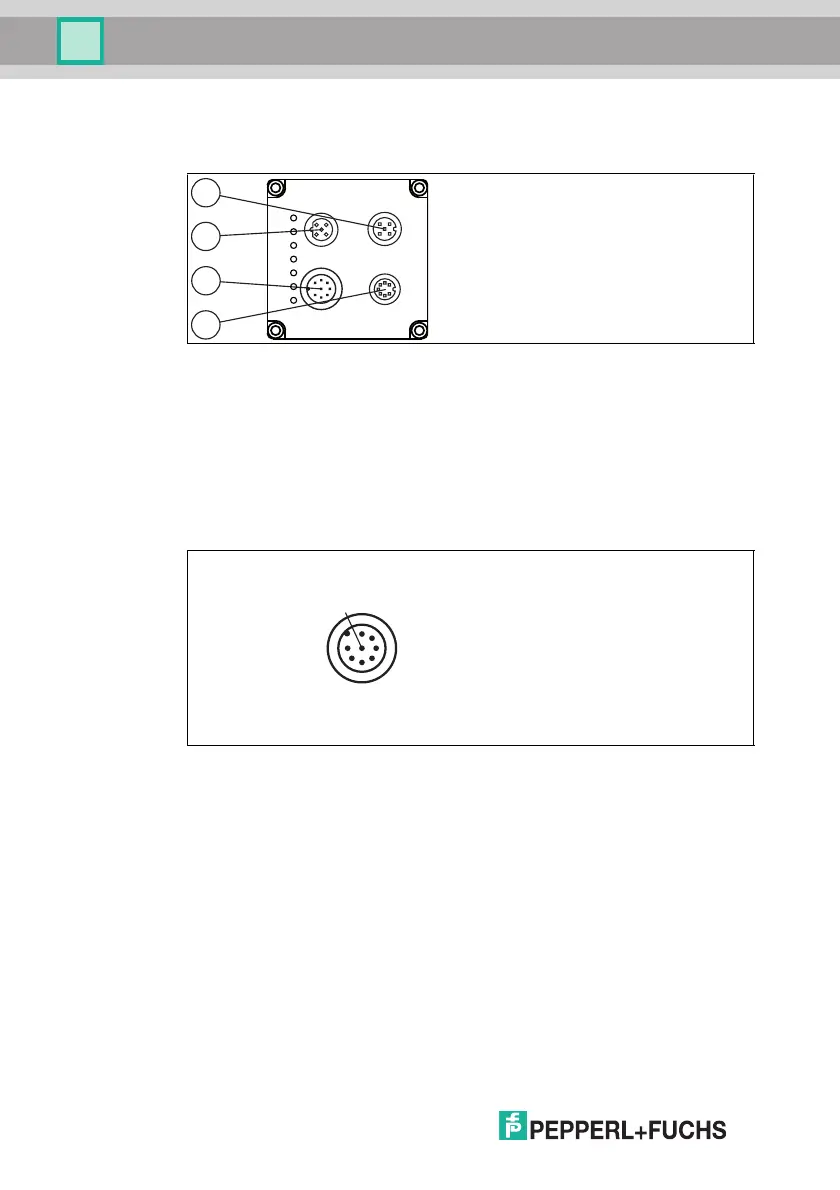
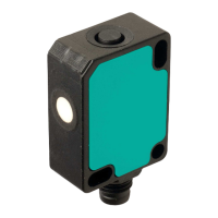
OPE reader
The device includes the following connections:
1. RS-232 interface (5-pin M12 socket)
2. Network (4-pin M12 socket)
3. Power supply, inputs, and outputs (8-pin M12 plug)
4. VGA output (7-pin M12 socket)
Power Supply
There is an 8-pin M12 plug on the back of the sensor housing to connect the
power supply, and to the inputs and outputs. The following diagram shows the
pinning:
Figure 4.6 Connection layout for operating voltage, and inputs and outputs
1. IN TRG / OUT 1
2. +UB
3. OUT Good / IN 1
4. OUT Fail / IN 2
5. IN 3
6. IN 4 / OUT 2
7. GND
8. OUT Match
Pin 1, pin 3, pin 4, and pin 6 have dual assignments, but these dual assignments
are not currently supported by the software: OUT 1, IN 1, IN 2, IN 3, IN 4 are
intended for future applications.
3
4
2
1
LAN
TRG
Fail
Status
PWR
LAN
RS 232
24VDC + IO
VGA
Match
Good