OPC / OPD / OPE
Product Description
2015-07
15
Network
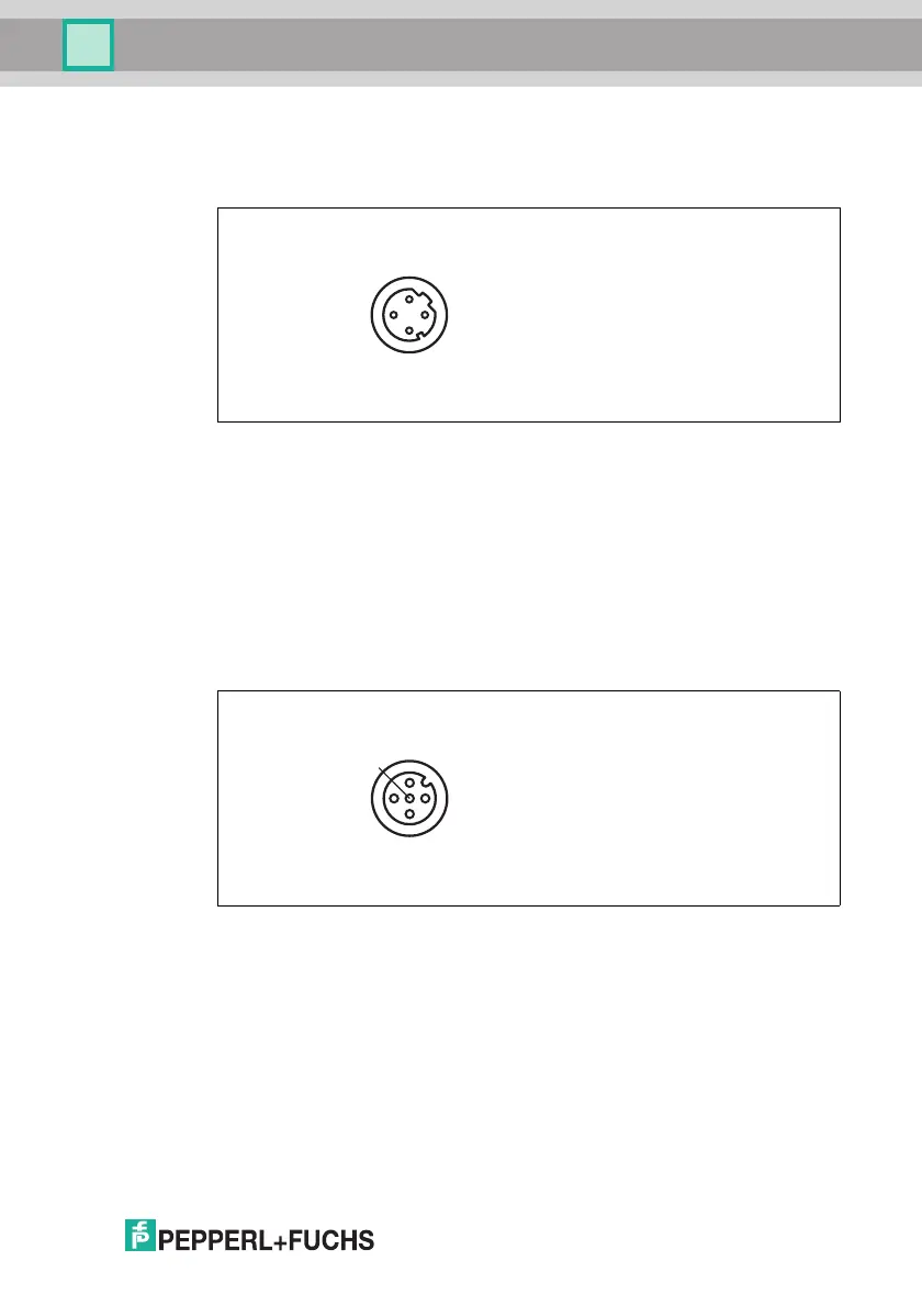
There is a 4-pin M12 socket on the back of the sensor housing to connect to the
network. The following diagram shows the pinning:
Figure 4.7 Network connection layout
1. TX+ Ethernet
2. RX+ Ethernet
3. TX- Ethernet
4. RX- Ethernet
RS-232 Interface
There is a 5-pin M12 socket on the back of the sensor housing for connecting the
RS-232 interface or external lighting. When using as the RS-232 interface, do not
connect any cables to pin 1 or pin 5. The following diagram shows the pinning:
Figure 4.8 RS-232 connection layout
1. +UB
2. TX RS-232
3. GND
4. RX RS-232
5. IN 5 / OUT 3