2015-07
32
OPC / OPD / OPE
Vision Configurator Software
Network
Other
Digital I/O
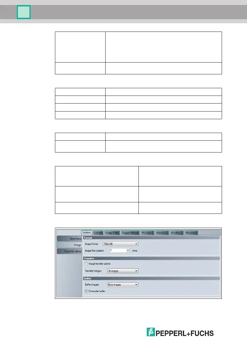
Figure 7.9 System tab, Image menu item
Parity mode Setting for detection of transmission errors
■ None
■ Odd
■ Even
Result output via TCP/IP
Trigger string Definition of the trigger string that can be used to trigger a
trigger command via the RS-232 interface
Enable TCP/IP result Result output via TCP/IP
Enable UDP result Result output via UDP (User Datagram Protocol)
TCP/IP port Entry of the corresponding port
UDP port Entry of the corresponding port
Position LEDs Activation of the position LEDs
Sensor name Enter a device name for the sensor. The device name can be
used instead of the IP address to connect to the sensor
Pulse length GOOD [ms] Length of the output signal for a successful
read
Value range: 0 ... 30,000 ms
0 means that the output signal is not reset
Pulse length BAD [ms] Length of the output signal for a failed read
Value range: 0 ... 30,000 ms
0 means that the output signal is not reset
Trigger delay [ms] Delay for a trigger
Value range: 0 ... 30,000 ms
System Tab, Image Menu Item