5.1 Pass/Fail Output
via
USB Connector
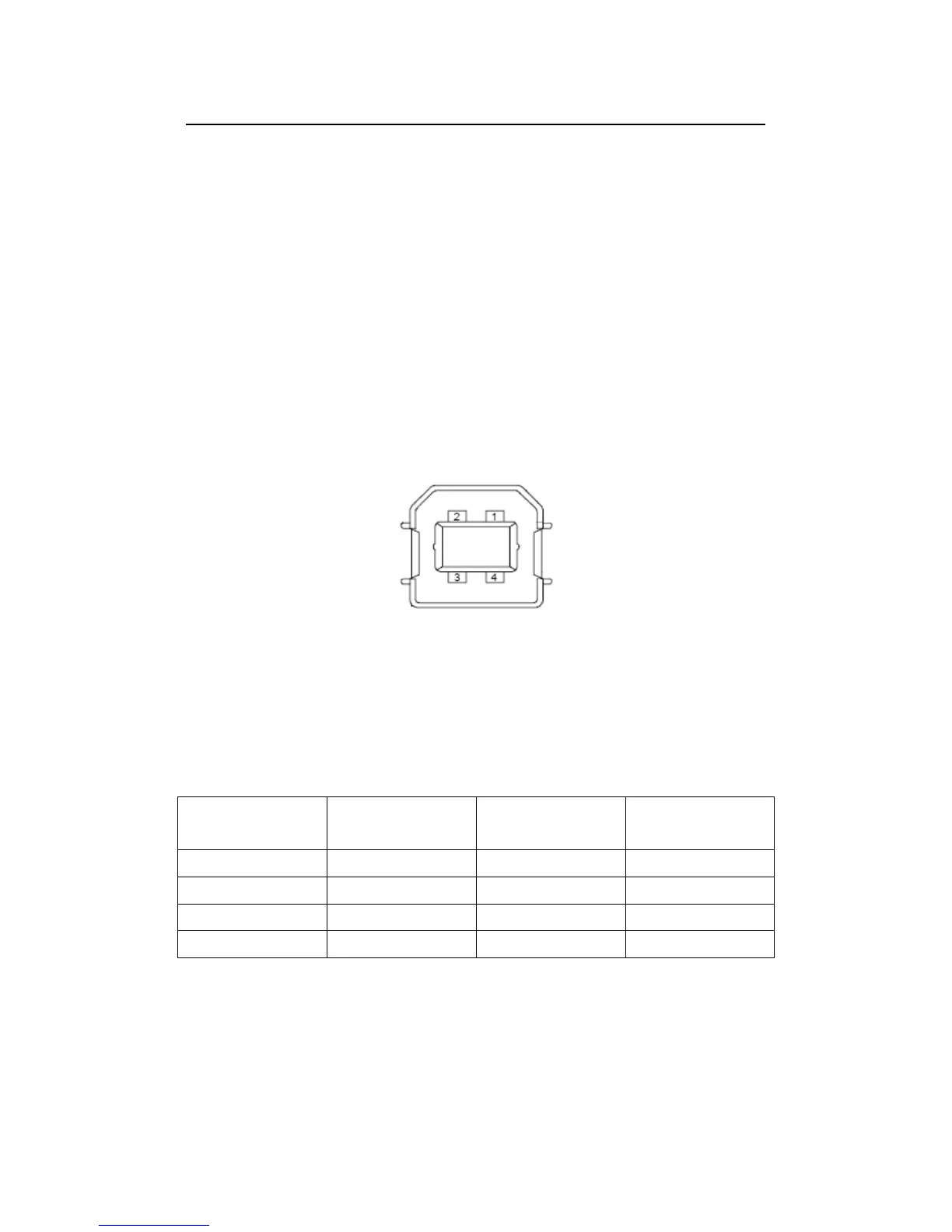
The USB connector, which comforns to USBTMC protocol, on the rear
panel of M3500A is a series “B” connector. When the USB interface is
disabled (IEEE-488 interface is selected), the internal pass and fail TTL
output signals (limit testing) will be transmitted via the USB port.
The pass and fail signals are low true and indicate the Math Pass/Fail
Limit Test result for the next reading to be output to the GPIB interface.
The signals are active low for approximately 2ms (
sec) for each
reading taken. Figure 2-17 shows the USB connector (series “B”). And
Table 5-1 shows the detailed connector information.
Figure 2-17
Table 5-1
If you disable the USB interface, the Pass/Fail output function will enable
automatically. Please follow the procedure below to enable/disable this
function.
Procedure: MENU
ENABLE/DISABLE
Or you can do this by the other way:
Contact
Number
Signal Name
Typical Wiring
Assignment
Description
1 VBUS Red Floating
2 D- White Limit Test Pass
3 D+ Green Limit Test Fail
4 GND Black GND