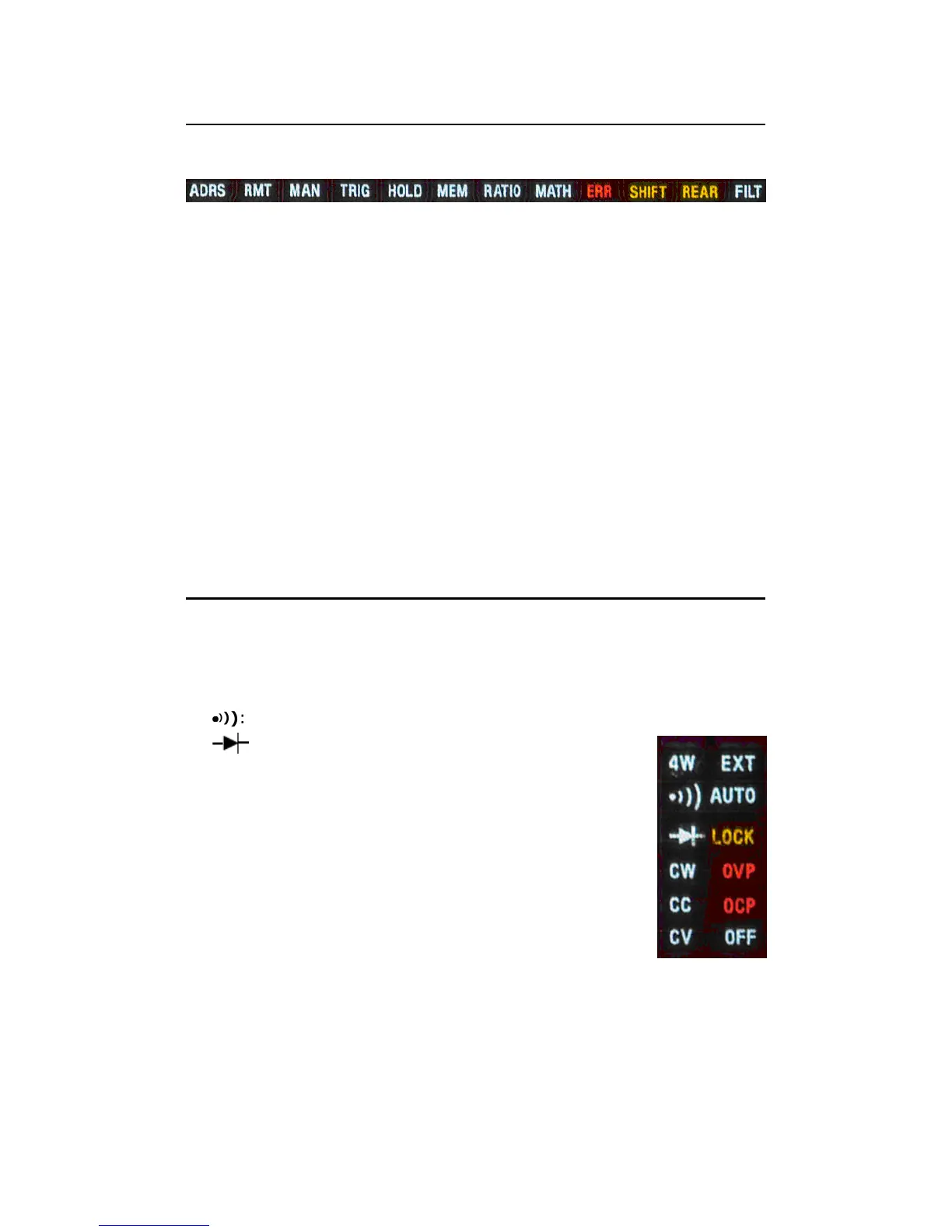
2.3.2.1 Annunciators at Upper Side
Figure 2-18
ADRS: Indicates the multimeter is controlled via GPIB Interface.
RMT (REMOTE): Indicates the remote state. (USB Interface)
MAN: Indicates the manual range is taken.
TRIG: Shows the single triggering is enabled.
HOLD: Indicates reading hold function is enabled.
MEM: Indicates the using of internal memory.
RATIO: Indicates the dcv:dcv ratio operation.
MATH: Indicates the “MATH” operation is taken.
ERR: Error occurs.
SHIFT: Indicates SHIFT button is pressed.
REAR: The rear panel input terminal is selected for the measurement.
FILT: The digital filter is started.
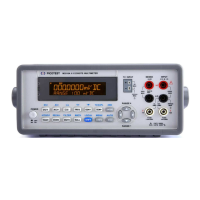
2.3.2.2 Annunciators at Right Side
4W: Indicates 4 –wire mode is selected for resistance measurement.
●
●●
●
)
)
): Indicated the continuity testing is enabled.
: Indicates the diode testing operation is taken.
CW: Not used for Model M3500A.
CC: Not used for Model M3500A.
CV: Not used for Model M3500A.
EXT: Indicates the External Trigger Mode is enabled.
LOCK: Indicates the front panel menu operation
is locked.
OVP: Not used for Model M3500A.
OCP: Not used for Model M3500A.
OFF: Indicates the front panel display is turned off. Figure 2-19