2.3.3 The Rear Panel
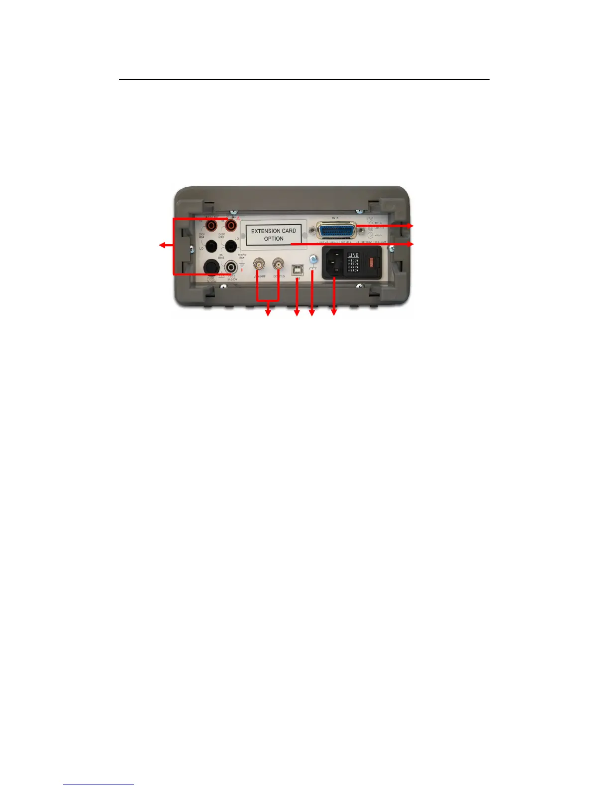
The rear panel of the M3500A is shown in Figure 2-20. This figure
includes important abbreviated information that should be reviewed
before using the instrument.
Figure 2-20
1. Inserted Connections & Fuse Device:
HI & LO: Used for all measurements, except AC & DC current and
temperature.
LO & I: Used for making DC and AC current measurements.
Rear Fuse: Secures your Meter against damage of strong current
pulse.
2. BNC Connections:
VM COMP: Voltmeter Complete Output Terminal. Outputs a low-true
pulse after the completion of each measurement.
EXT TRIG: External Trigger Input Terminal. Inputs a low-true pulse
from a remote interface.
3. USB Connection: Connects a remote computer for changing
operation environment instead of the front panel control.
4. Chassis Ground: Used for shielding the noise from the nature.
5. Power Module: Contains the AC line receptacle, power line fuse, and