Do you have a question about the Polaris 2001 50 SCRAMBLER and is the answer not in the manual?
Identifies vehicle using a 17-character code.
Locates the engine model and serial number for identification.
Locates the machine model and serial number for vehicle identification.
Provides technical data for various models like Scrambler and Sportsman.
Lists model and owner's manual part numbers for service.
Lists paint colors and corresponding Polaris and Ditzler numbers.
Provides torque values for common fasteners across different vehicle components.
Lists part numbers for lubricants, grease, and additives.
Table for converting Newton Meters to Pound Feet and Pound Inch.
Chart converting fractional inch measurements to decimal equivalents.
Table for converting various units of measure, including temperature.
Lists drill sizes for various SAE thread sizes.
Lists drill sizes for various metric thread sizes.
Defines technical terms used throughout the manual.
Outlines recommended service intervals for various vehicle components.
Details how to inspect and adjust front brake lever free play and travel.
Details how to inspect and adjust rear brake lever free play and travel.
Describes how to adjust chain tension and torque related bolts.
Recommends lubricant type and frequency for spindles.
Guides inspection of front shocks and springs for proper function and damage.
Guides inspection of rear shocks and springs for proper function and damage.
Advises checking wheel nut tightness and re-torquing monthly.
Provides steps to check and change transmission lubricant level and procedure.
Describes how to check throttle lever operation for smoothness and binding.
Details the procedure for adjusting the carburetor air screw for fuel mixture.
Explains how to adjust the engine idle speed.
Details adjustment of throttle cable freeplay and ETC switch.
Continues adjustment of throttle cable freeplay and ETC switch.
Outlines the steps for adjusting the oil pump cable and arm.
Provides instructions for bleeding air from the oil pump system.
Lists common issues and steps to verify oil delivery to the engine.
Advises checking fuel lines for wear, damage, and proper routing.
Advises checking vent lines for wear, damage, and proper routing.
Provides steps for replacing the fuel filter.
Explains how to drain the carburetor float bowl for maintenance.
Details the procedure for performing a cylinder compression test.
Describes how to inspect, clean, or replace the air filter element.
Lists torque specifications for wheel, hub, and spindle components.
Provides instructions for removing and installing vehicle wheels.
Specifies tire pressure requirements and inspection notes.
Details checking tire tread depth and proper tire replacement.
Advises periodic inspection of fastener torque and cotter pins.
Describes using a straightedge or string to measure toe alignment.
Details using chalk marks to measure and set vehicle toe alignment.
Provides steps for adjusting toe alignment by modifying tie rods.
Lists torque values for engine components like crankcase, cylinder head, and spark plug.
Lists special tools required for engine service and their part numbers.
Provides general guidelines and break-in procedures for engine installation.
Step-by-step instructions for disassembling the engine, starting with fan cover.
Steps for removing fan cover, air shroud, deflector, and fan.
Instructions for removing the starter motor from the engine.
Steps for removing air duct, carburetor, intake manifold, and reed valve.
Instructions for removing spark plug and inspecting for wear.
Steps to remove cylinder head, cylinder, and inspect for scoring.
Instructions for removing piston pin circlips, pin, piston, and rings.
How to carefully remove piston rings without damage.
Steps for removing transmission cover, bolts, and bracket.
Instructions for removing kick starter, bolts, and crankcase cover.
Steps to remove drive clutch nut, washer, and fixed sheave.
Steps to remove the belt, primary clutch sheave, and clutch assembly.
Instructions for removing idle gear bolts, plate, shaft, washers, and idle gear.
Steps for removing starter clutch, starter gear, bearing, and washer.
Instructions for draining oil, removing transmission cover, and shaft components.
Steps to remove flywheel nut, washer, flywheel, and stator assembly.
Instructions for removing the oil pump and its drive gear.
Steps to disassemble crankcase halves and remove the crankshaft.
Instructions for removing the external snap ring and oil seal.
Inspects cylinder head for warpage and gasket residue.
Inspects cylinder for warpage, wear, damage, and out-of-round.
Inspects piston for scoring, cracks, carbon buildup, and clearance.
Measures installed piston ring gap and checks against service limit.
Measures piston pin hole diameter and checks against service limit.
Inspects piston pin surface and measures its diameter against service limit.
Inspects connecting rod small end for wear and checks bearing.
Measures air gap between reed and block, checks fiber reeds.
Inspects clutch cover diameter and brake lining thickness.
Inspects compression spring length against service limit.
Inspects drive belt for wear, deposits, and measures width.
Guide to selecting and performing cylinder honing for proper ring seating.
Measures crankshaft runout at MAG and PTO sides against service limits.
Steps for installing oil seal, crankshaft, gasket, and crankcase bolts.
Instructions for installing oil pump bracket and drive gear.
Steps for installing oil pump, stator, and torque bolts to specification.
Inspects flywheel key and installs flywheel, torquing nut to spec.
Instructions for installing driven clutch shaft components.
Installs transmission cover, torques bolts, and adds gear case oil.
Steps for installing starter clutch, gear, needle bearing, and idler gear.
Installs driven clutch, nut, and torques to specification.
Installs primary clutch sheave and drive belt.
Installs primary fixed sheave and claw washer.
Installs drive clutch bolt and torques to specification.
Installs crankcase cover and bracket for Sportsman/Scrambler 90.
Installs crankcase cover and bracket for Scrambler 50.
Installs small end bearing, piston rings, base gasket, piston, and pin.
Instructions for installing new circlips.
Installs cylinder, head gasket, and head, torquing to specification.
Installs new spark plug and checks gap.
Installs intake manifold, reed valve, and torques bolts.
Installs carburetor and tightens adapter screw.
Installs air duct to carburetor.
Installs starter motor and torques bolts to specification.
Installs fan and torques bolts to specification.
Installs cylinder air shroud and deflector, torquing screws.
Installs fasteners on fan cover and torques bolts to specification.
Lists common causes for spark plug fouling.
Lists causes for engine not starting despite turning over.
Lists causes for engine not turning over at all.
Lists causes for engine running poorly at idle.
Lists causes for engine idle but inability to increase RPM.
Lists causes for engine lacking power.
Lists causes for piston scoring.
Lists causes for excessive smoke and carbon buildup.
Lists causes for low cylinder compression.
Safety warnings regarding handling gasoline and fuel system operation.
Explains the function of a carburetor and its systems.
Describes the float system's role in maintaining fuel level.
Explains the function of the pilot jet in fuel metering at low speeds.
Describes the jet needle's role in fuel metering and adjustment.
Explains how the needle jet works with the jet needle to regulate fuel flow.
Illustrates how fuel flow changes with throttle opening.
Explains how the throttle valve controls air intake and fuel flow.
Describes the main jet's role in metering fuel at higher throttle openings.
Explains the pilot system's role in metering fuel at idle and low speeds.
Describes the effect of slide cutaway on air/fuel ratio at part throttle.
Explains how jet needle/needle jet affect mixture at medium throttle.
Describes the main system's role in delivering fuel at mid-range and high throttle.
Demonstrates component relationship to fuel flow versus throttle opening.
Table detailing carburetor systems, components, and main functions.
Explains the function of vent lines for pressure regulation.
Details how to measure and adjust float height.
Procedure to test needle and seat for leaks.
Explains how to drain the carburetor float bowl for maintenance.
Diagram showing carburetor components and their part numbers.
Lists symptoms and causes of lean fuel mixture.
Lists symptoms and causes of rich fuel mixture.
Lists symptoms and causes of poor idle condition.
Lists causes for engine idle speed being too low.
Lists causes for engine idle speed being erratic.
Lists torque values and special tools for body and steering components.
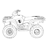
Illustrates side, front, and rear views of the vehicle frame.
Details the process of mounting the engine to the vehicle frame.
Describes mounting and adjustment of front and rear shocks and springs.
Instructions for mounting A-arms, spindles, and torquing related bolts.
Details greasing and mounting the steering post and its clamps.
Installs steering nut, bearing, and associated hardware.
Mounts tie rods to steering post and spindle, tightens bolts.
Components of the front brake backing plate assembly.
Inspects front brake shoe and drum for damage, bearings, and seals.
Mounts front brake assembly on spindle and tightens nut.
Diagram of rear brake and axle assembly parts.
Installs swing arm, rear shock, and spring, torquing bolts.
Mounts rear brake plate, shoes, springs, and brake drum.
Installs rear axle and drive sprocket, snugging bolts.
Installs spacer tubes and wheel hub, tightening axle nut.
Sets chain tension by adjusting chain adjuster and nuts.
Installs rear cover and torques bolts to specification.
Installs fuel tank and tightens mounting bolts.
Installs oil tank and fills oil reservoir.
Installs front bumper and tightens mounting bolts.
Installs front and rear cab sections to frame.
Describes right/left brake levers and left control switch on handlebar.
Details engine stop, start switch, and parking brake function.
Mounts handlebar on steering post and tightens clamp bolts.
Installs front and rear brake cables and checks lever play/travel.
Greases and installs throttle cable into ETC switch housing.
Installs the plate and handlebar cover.
Connects muffler to cylinder and frame, checking gaskets.
Lists electrical testing tools like multimeters and tachometers.
Provides important notes for diagnosing electrical problems.
Steps for replacing the brakelight bulb.
Procedures for servicing new batteries with electrolyte and charging.
Inspects battery fluid level and provides removal instructions.
Steps for cleaning terminals and installing the battery.
Introduces battery tests: OCV, Specific Gravity, and Load Test.
Explains using a hydrometer to measure electrolyte strength.
Details performing a load test to check battery capacity.
Guidelines for storing batteries to prevent damage during non-use.
Procedure for charging batteries to achieve specific gravity.
Identifies main electronic parts: regulator, resistor, CDI, coil.
Procedure to check for excessive current draw with the key off.
Step-by-step check for charging system issues.
Diagram of the ignition system wiring.
Measures ignition coil resistance and spark plug cap resistance.
Specifies ignition timing degrees for different models.
Flowchart for diagnosing no/intermittent spark issues.
Tests component output using a peak reading voltmeter.
Tests CDI output to coil using a peak reading adaptor.
Step-by-step procedure to test the charging system.
Tests the RPM at which the charging system starts to charge the battery.
Measures AC amperage output from the alternator.
Lists causes for the starter motor not turning.
Lists causes for the starter motor turning over slowly.
Lists causes for starter turning but engine not rotating.
Explains how to test connections for voltage drop.
Troubleshooting steps for a starter that fails to turn the motor.
Instructions for disassembling the starter motor casing.
Inspects and replaces starter motor brushes.
Tests armature resistance, commutator, and checks for shorts.
Steps for assembling the starter motor housing.
Tests the ETC switch function and throttle cable adjustment.
Lists causes for ignition system problems like no spark.
Electrical wiring diagram for the 2001 Scrambler 50 model.
Electrical wiring diagram for 2001 Scrambler 90 and Sportsman 90.
| Brand | Polaris |
|---|---|
| Model | 2001 50 SCRAMBLER |
| Category | Offroad Vehicle |
| Language | English |





 Loading...