3 - 24
Strobe Board, Erect Latch, and Cone Assembly
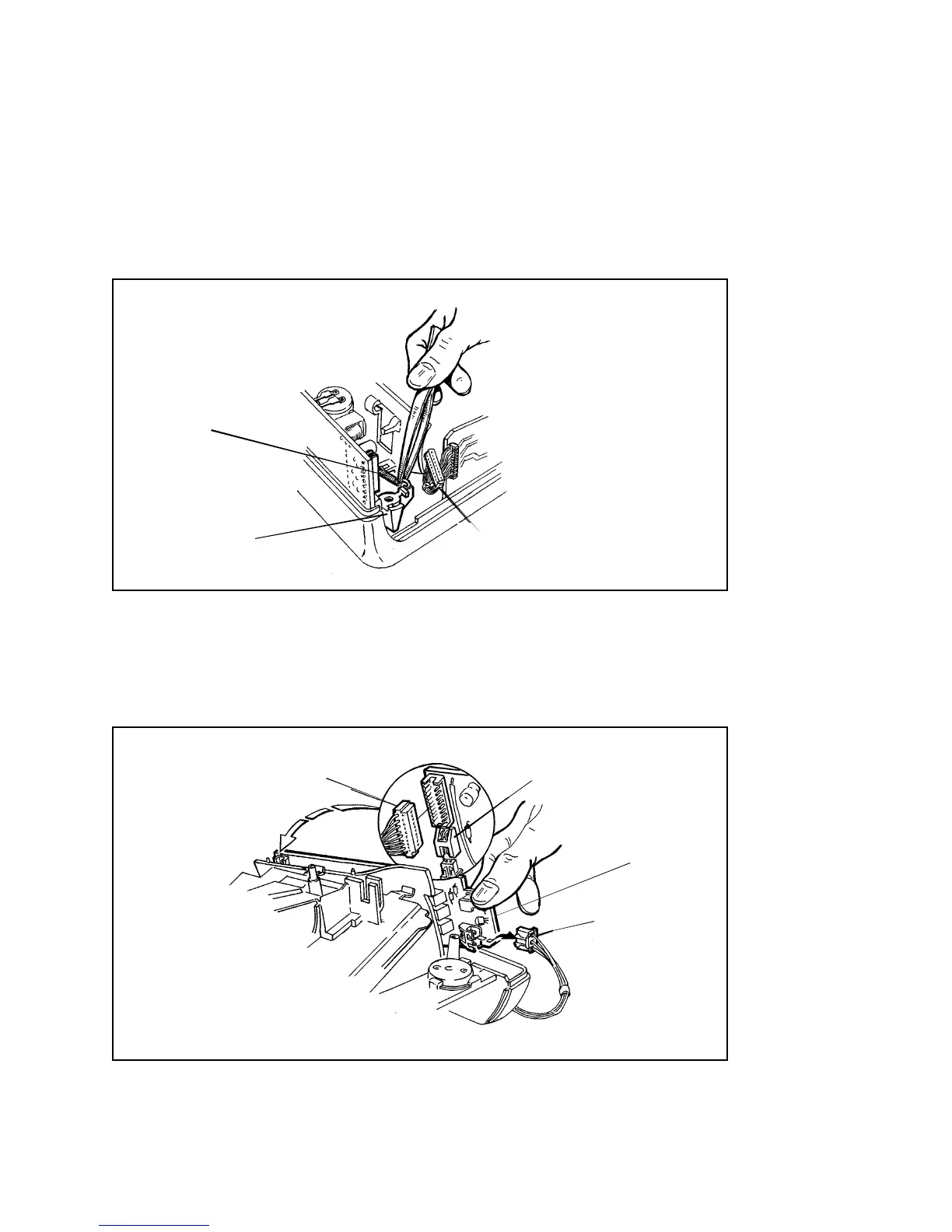
1. Removal
a. Lift the cabling from the Interface Board out of the way, to gain access
to the Erect Latch Spring (Figure 3-21). Now unhook one end of the
Erect Latch Spring from the Erect Latch.
Figure 3-21. Unhooking Erect Latch Spring
b. Lift one end of the Strobe Board and disconnect the Erect Switch (J15),
Interface Board (J17) and Battery connectors (J16) from the Strobe PC
Board (Figure 3-22).
Figure 3-22. Disconnecting Erect Switch (J15), Interface Board (J17)
and Battery cables (J16) from Strobe Board
J 17
J 16
J 15
STROBE BOARD
J 17
SPRING
ERECT LATCH
(F ROM INTERFAC E BOAR D)
(F ROM INTERFACE B OAR D)
(F ROM BATTERY)
(FROM ERECT SWITCH)

 Loading...