955725_4
61
Diagnose
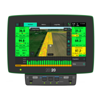
The Diagnose Menu is the primary location for
trouble shooting issues related to the operation of
the 20|20 system itself and all products
configured on the monitor. This is the initial
diagnose page. Each product or system that is
configured is displayed along with a row unit
showing a drawing of the product(s).
Additionally, there is bar at the top of the screen
displaying the health of each row.
Each of the categories on the main (1st level) diagnose page can be selected to show further
details about that system or product.
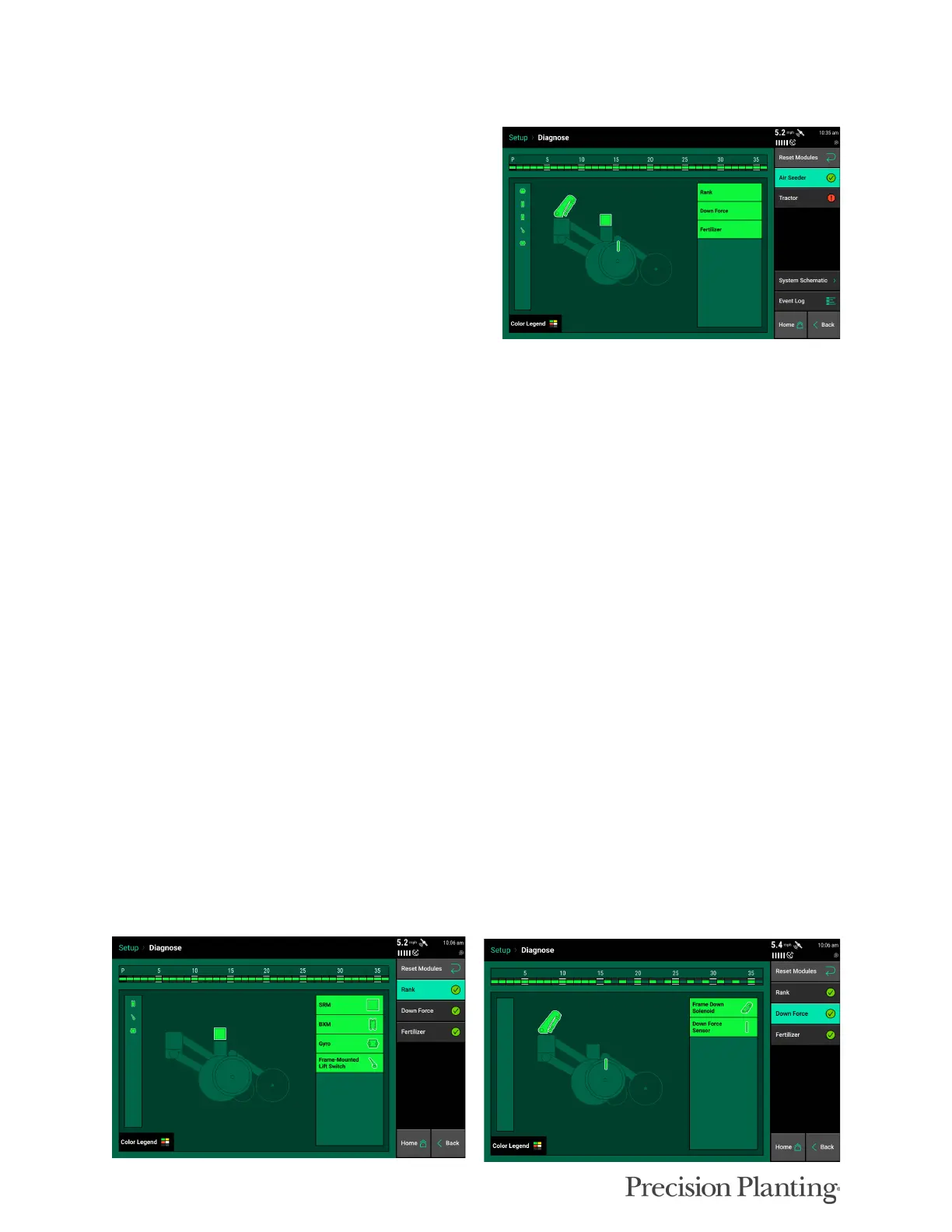
The following is a tree or list of where modules are generally listed on most Air Seeder systems.
Location may change depending on configuration
• Rank
• SRM: Voltage and Bus CAN errors of all SRMs
• Lift Switch: current position and state
• Gyro: current acceleration and turn rate
• BXM: Voltage and Bus CAN errors of BXM modules (does not include state of BXM
inputs)
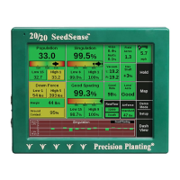
• Downforce
• Frame Down Solenoid or SeederForce Row Solenoid: Commanded psi and current
duty cycle
• Down Force Sensor: lbs- current measured weight on down force sensor
• Fertilizer, Wheat, or other Product Name
• BXM Input: current state of Flow on each BXM input
• Rate Control (when applicable): Rate, commanded Rate, Motor speed, Motor speed
command, Duty cycle, Voltage
• Blockage Sensor (when applicable): Flow state, supply voltage