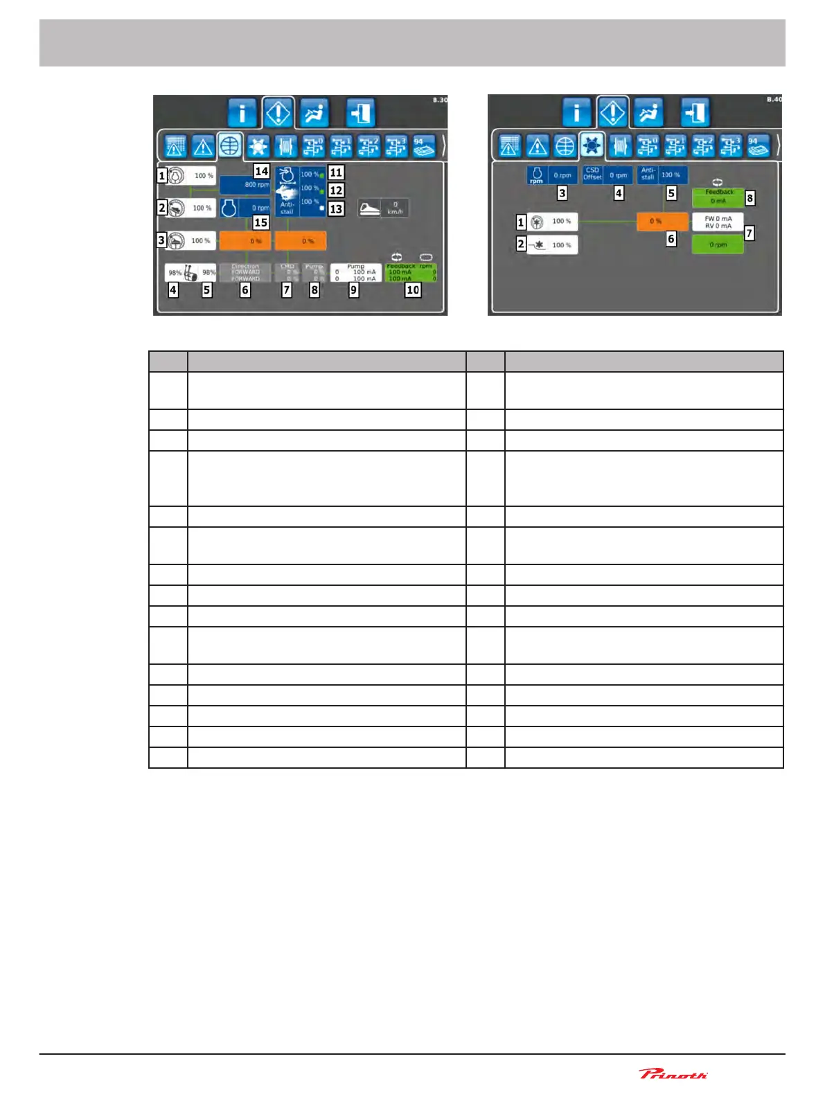
Figure 42: Input / output traction drive (B.30) || Input / output tiller drive (B.40)
Pos. Input / output traction drive (B.30) Pos. Input / output tiller drive (B.40)
1 Engine RPM potentiometer (hand throttle
potentiometer)
1 Rear tiller rotary switch
2 Accelerator pedal 2 Cutting angle
3 Vehicle speed (Inch potentiometer) 3 Acutal diesel engine speed
4 Control lever (FNR) left (excursion in %) or
steering wheel
4 Actual hydraulic motor RPM (actual value)
–
sensor is mounted in the hydraulic motor
of the tiller
5 Control lever (FNR) right (excursion in %) 5 Anti-stall
6 Control lever (FNR) position (forward - neu-
tral - reverse)
6 Tiller pump – actual command for the tiller
pump
7 Control lever (FNR) (default value in %) 7 Tiller pump – RPM + Current
8 Drive pump (default value in %) 8 Tiller pump – feedback current
9 Pump current
10 Pump current feedback signal - RPM final
drive
11 Air filter clogging
12 Overspeed RPM
13 Anti-stall - maximum load control
14 Default engine RPM (set value)
15 Acutal RPM (actual value)
Snow groomer BISON
Operating and Maintenance Manual
BISON 908930245 - 30367
6 - Display
89 (255)