5–11Replacement Procedures
Card cage floor
Front
Shuttle Frame
Assembly
Hammer Bank
Fan
Card
Cage
Fan
Paper feed mechanisms
and barrier panel
Platen
Base casting
Platen
open
motor
Paper
feed
motor
(PCBAs removed)
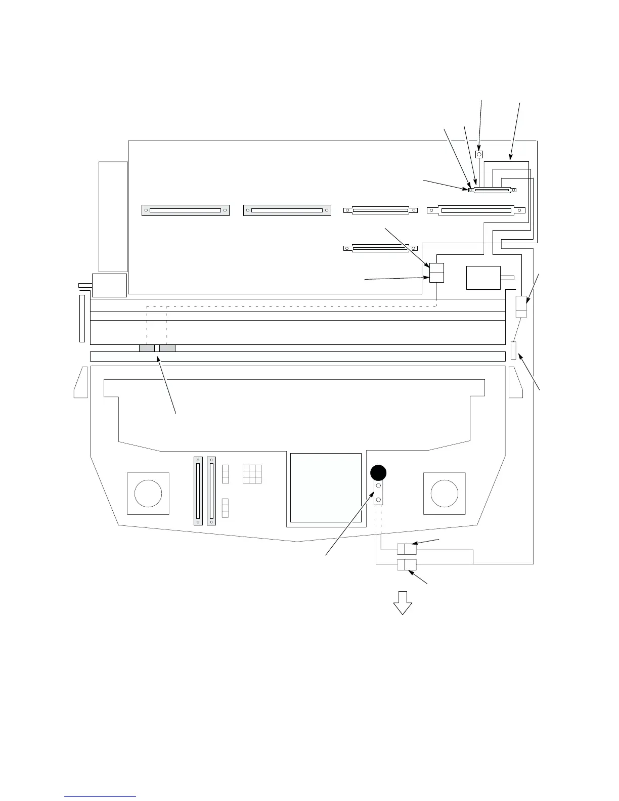
1. Screw (2) (Scr, w/LW, 4–40x.75)
2. Intermediate Cable Assy Connector P1 (p/o item 10.)
3. Connector P1(P) (p/o item 10.)
4. Platen Interlock Switch Assembly (P/N 150284–001)
5. Connector PMD (J) (p/o item 10.)
6. Connector PMD(P) (p/o Paper Detector Switch Assembly)
7. Cover Open Switch Assembly (P/N 150296–001)
8. Connector CO+ (p/o item 10.)
9. Connector CO– (p/o item 10.)
10.Intermediate Cable Assembly (P/N 150286–001)
1
2
3
4
5
6
8
9
7
This section of cable runs
beneath the base casting.
Paper detector
switch assembly
Printer viewed from above, PCBAs removed.
J
P
P
P
P
Ground Lug
10
Pin 1
Figure 5–4 . Cable Assembly, Intermediate, Removal/Installation