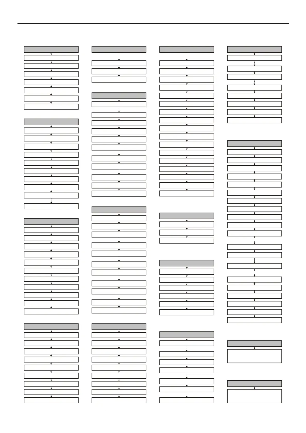
1 - Operation mode
1-1 control ref. signal
1-2 regulation ref. signal
1-3 selection
1-5 control
1-6 regulation
1-7 feedback
1-8 modification
1-10 PID settings
1-11 PID 1 data
1-14 PID 4 data
2-10 fly snips
2-11 flying start
2 - Starts
2-1 rise time
2-2 acceleration
2-3 multistep acceleration
2-4 S curve
2-5 start disable
2-6 direction change disable
2-7 restart
2-8 start type
2-9 brake release
3 - Stops
3-1 fall time
3-2 deceleration
3-3 multistep deceleration
3-5 stop type
3-6 normal brake
3-7 free time
3-8 DC brake
3-9 resistor brake
3-10 Udc hold
4 - Inputs
4-1 analogue input 1.
4-4 analogue input 4.
4-8 logical control source
4-9 logical parameters
4-10 fix start
4-11 digital input 1.
4-21 virtual input 1.
4-18 digital input 8.
4-26 virtual input 6.
4-30 slave data
4-31 IRE data
5 - Outputs
5-1 analogue output 1.
5-2 analogue output 2.
5-11 digital output 1.
5-16 timing 1.
5-21 comparator 1.
5-26 period 1.
5-13 digital output 3.
5-18 timing 3.
5-23 comparator 3.
5-28 period 3.
5-29 PID extension
10 - Displays
10-1 row 1.
10-4 row 4.
10-7 productivity 1.
10-10 4.productivity
10-12 big characters
10-11 user define units
10-13 consumption meter clear
10-14 active menu
11 - System
11-1 parameters
11-4 macro
11-5 remote control
11-6 modulation
11-7 slip-compensation
11-8 output
11-9 language
11-10 CAN bus
11-12 terminal function
11-13 automatic error ackn.
11-14 save event
11-18 manufacturing number
11-19 software version
11-20 date
11-21 currents
11-22 voltages
11-23 special data
11-24 clear log
11-25 password
11-27 menus with password
READ ONLY
PASSWORD PROTECTED
0 - Quick menu
0-1 control Tup
0-2 control Tdown
0-3 motor In
0-4 f maximum
0-5 f minimum
0-6 U boost
0-7 active menu
12 - Events
The event log can store
256 events along with
the belonging point of times.
13 - Errors
The error log can store
256 errors along with
the belonging point of times.
6 - Motor
6-1 nominal power
6-2 nominal voltage
6-3 nominal frequency
6-4 nominal current
6-5 nominal rotation speed
6-6 cooling type
6-7 limit
6-9 torque limit
6-10 test
6 - Motor
6-12 n maximum
6-11 R stator meas.
6-13 R stator
6-14 L stator
6-15 magnetizing current
6-16 linearity of the magn. current
6-17 exponent of the magn.current
6-18 R rotor correction
6-19 nominal start time
6-20 I regulator
6-22 n regulator
6-23 field weakening
6-24 sensorless
6-25 blocking
6-26 R rotor adaptation
6-27 sync. offset
6-28 type
continued
7 - U/f ratio
7-1 characteristic types
7-2 U/f modification
7-3 user characteristic
8 - Frequencies
8-1 f maximum
8-2 f minimum
8-3 frequency inhibit limit
8-4 jog normal
8-5 jog inverse
8-6 inhibited bands
9 - Programs
9-1 counter 1.
9-3 3.counter
9-10 program activation
9-11 program 1.
9-25 program 15.
9-26 sequence 1.
9-28 3.sequence
3-11 brake operation
3-12 Udc filter
3-13 emergency fall time
3 - Stops
continued