H - I - J PROGRAMMER’S MANUAL V8.94.11-
- 80 -
Programming guide
Below, sample programs are shown for some frequently used control and regulation tasks.
They may help at programming.
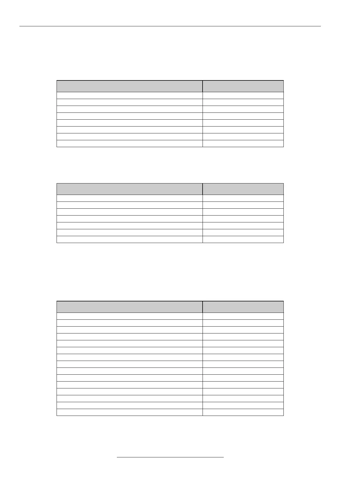
Control from terminal between 5 and 60 Hz
source of the control reference signal
digital input 1 type selection
digital input 2 type selection
The commands start, stop, direction and frequency change can be given from the terminal.
Control from terminal blocks with potentiometer between 10 and 50 Hz
At the lower extreme position of the potentiometer the driven unit has to stop.
source of the control reference signal
analogue input 1. stop range
analogue input 1. hysteresis
The commands start, stop and direction, can be given through the digital terminal blocks (SD), the frequency can be
changed with the potentiometer connected to the analogue terminal blocks (SA).
The lower extreme position of the potentiometer sets “waiting” mode!
Control from terminal, reference signal change between 1 and 100 Hz with motor potentiometer
function
The motor potentiometer function should be activated from the Digital IN1 and IN2 inputs or from the terminal!
source of the control reference signal
digital input 1 type selection
digital input 2 type selection
digital input 4 type selection
digital input 5 type selection
motor potentiometer up time
motor potentiometer down time
motor potentiometer clear
The commands start, stop and directions can be given from the terminal.
Changing the frequency can be effected with Digital IN 4. and IN 5. or in display mode with the terminal push buttons
and (motor potentiometer up and down).