H - I - J PROGRAMMER’S MANUAL V8.94.11-
- 79 -
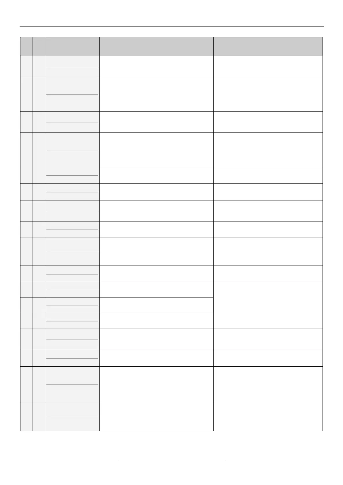
Short description of the error
Par.err.An.IN1-4
(P.An.IN1-4)
Insufficient parameter selection for the
given number of analogue inputs. (The
selected input has more than one function.)
Checking and improving the setting of the
parameter
Parameter error
(Par.err.)
Not coherent parameters have been
selected to the selected mode.
(e.g. flying start with brake loosening, at
master equipment source of reference
signal CAN)
Checking and improving the setting of the
parameter
Not user macro
(Non user)
At macro copying, in 11-4-2 not a user
macro is selected. Copying cannot be
performed.
In menu 11-4-2 selecting user macro 1, or
user macro 2 then copying.
Error in the saved data.
(e.g. not proper value in the parameter
table)
By pressing the exit button, the program
skips to the wrong parameter. The
parameter is offered with the factory value.
In case of several faulty parameters, the
program shows them in line.
EEPROM write er.
(EEPROMwr)
Internal error. The manufacturer is
required to troubleshooting.
Indicates error in the internal
communication (I
2
C). (clock, EEPROM)
Internal error. The manufacturer is
required to troubleshooting.
Interface error1
(Interfac)
No connection with the unit performing the
procession of the analogue and digital
inputs.
Internal error. The manufacturer is
required to troubleshooting.
Interface error2
(Interfac)
Error in processing the analogue inputs or
several digital inputs.
Internal error. The manufacturer is
required to troubleshooting.
Par. CHKSUM err.
(Par.CHKS)
CHKSUM error of the parameter set.
If this error occurred at powering the
equipment, the equipment will continue
operating with the factory settings.
Loading a proper parameter set saved
earlier, or repeated setting of the
equipment.
Turn off CHKSUM
(Turn off)
CHKSUM error of the switch-off buffer.
Internal error. The manufacturer is
required to troubleshooting.
Iu measure error
(Iu measu)
Large offset error of the motor current
measuring in the U phase.
Internal error. The manufacturer is
required to troubleshooting.
Iv measure error
(Iv measu)
Large offset error of the motor current
measuring in the V phase.
Iw measure error
(Iw measu)
Large offset error of the motor current
measuring in the W phase.
The error the frequency converter stopped
with cannot be defined.
If it occurs several times even after the
error has been cleared, the manufacturer
is required to troubleshooting.
Terminal 1 error
(Terminal)
Faulty parameter loading from terminal.
Loading of the proper parameter set.
Indicates error in the CAN transmissions.
(e.g. master/slave connection broken)
Check:
• if the master device is turned on and it
is set up as a master,
• CAN bus cabling
• Connections
MOD bus timeout
(MODB.to.)
In start state, the device did not receive a
message during the time set in the MOD
bus timeout.
Check:
• if the master device is turned on
• MOD bus cabling
• Connections
If the error cannot be repaired with the troubleshooting and acknowledgement described here, the manufacturer needs
to be contacted!