H - I - J PROGRAMMER’S MANUAL V8.94.11-
- 31 -
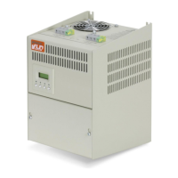
Start command with pulse control, from terminal blocks
(using a terminal similarly to the operation of the start and stop buttons)
The minimum pulse width will be established by the extent of debouncing, in 2ms steps (menu 4-9-5).
Direction change while running
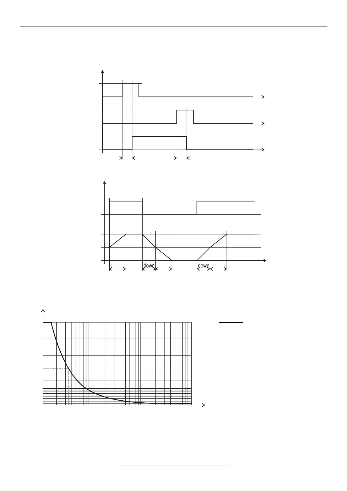
Permissible load of the brake resistor (typical curve)
The brake resistor must be of wire wound type. If the user provides the brake resistor, the rating, type and placement
must be consulted with the manufacturer.
Example:
Rbrake = 100 Ω
P (Rbrake) = 200 W
Ubrake = 660 V
P = 660V
2
/ 100Ω = 4356W
Overloading = 4356 / 200 = 21,78 (~22)
Starting from the overloading, the diagram
curve reads 3.5 s for the maximum value
of the braking time.
The interval between brakings should be
at least 22 x braking time!