H - I - J PROGRAMMER’S MANUAL V8.94.11-
- 33 -
In case of start command given with pulse, the possibility of stopping the motor has to be assured, e.g. by
programming an input to stop, spin out, DC brake, external error etc.
A requirement for the pulses, that they will only be accepted, if they exist in both logical state at least for the time of
the debouncing (2-32 ms, depending on the setting)
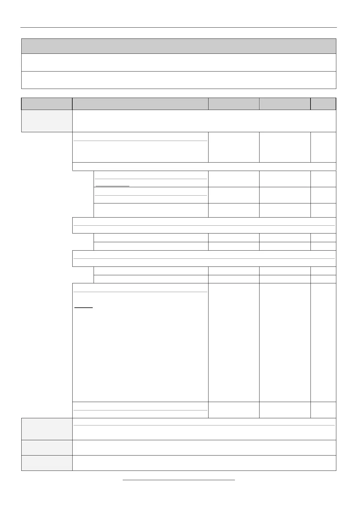
Explanation, further submenus
With setting the parameters, the character of the input is decided only!
The purpose, the input will be used for (control reference signal, regulation reference signal,
feedback signal, modification signal) is selected in menu 1. Operation mode.
4-1-1 type
The jumper belonging to the input has to be set
according to the equipment type (s. Manual).
(At V3D: A1, at VLD - VHD: A1P, A1N)
potentiometer
voltage
current
4-1-2-1 type
signed value: referring to the mid-position.
4-1-2-2 stop range
With setting “N” there is no stop range
4-1-3 voltage
Setting the upper and lower level.
4-1-4 current
Setting the upper and lower level.
4-1-5 function
Functions of the analogue IN1 input.
control: the control, reference and modification
signals can be entered.
The further functions permit the most important
parameters to be set during operation.
At the upper level of the analogue input the preset
value will be valid, at the lower level as follows
here:
rise time: a 50
th
part of the preset value
fall time: a 50
th
part of the preset value
U boost: 0 V
torque limit: a 10
th
part of the preset value
f max.: 5 Hz
f min.: 0.01 Hz
U motor: a 10
th
part of the preset value
control
rise time
fall time
U boost
torque
f max.
f min.
U motor
4-1-6 filter
For use to eliminate the influence of the ambience.
The setting is the same as that of item 4-1 analogue input 1.
The jumper belonging to the input has to be set according to the equipment type (s. Manual).
(At V3D: A2, at VLD - VHD: A2P, A2N))
The setting is the same as that of item 4-1 analogue input 1. (Optional)
Voltage input only. Current signal can be received with an external 500Ω termination resistor.
The setting is the same as that of item 4-1 analogue input 1. (Optional)
Voltage input only. Current signal can be received with an external 500Ω termination resistor.