CAUTION!
Danger from incorrectly operated or inadequately maintained
pumps
Danger can arise from a poorly accessible pump due to
incorrect operation and poor maintenance.
– Ensure that the pump is accessible at all times.
– Adhere to the maintenance intervals.
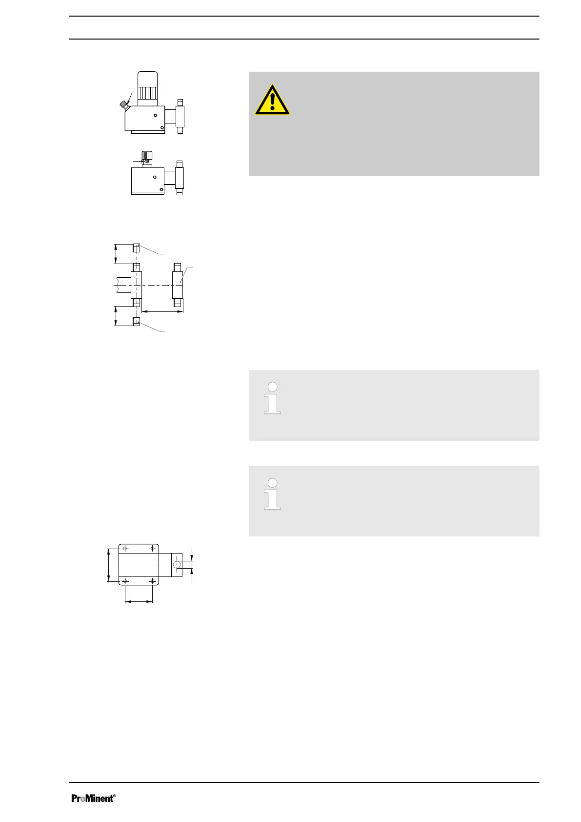
Position the pump so that control elements such as the stroke length
adjustment knob, the indicating dial A or the oil inspection window are
accessible.
In so doing, ensure there is enough space to carry out an oil change (vent
screws, oil drain plugs, oil trough ...).
1 Discharge valve
2
Dosing head
3 Suction valve
Ensure there is sufficient free space (f) around the dosing head as well as
the suction and discharge valve so that maintenance and repair work can
be carried out on these components.
Capacity too low
If the valves of the liquid end do not stand upright, they
cannot close correctly.
–
The discharge valve must be upright.
Capacity too low
Vibrations can disturb the valves of the liquid end.
–
Secure the metering pump so that no vibrations can
occur.
Take the dimensions (m) for the fastening holes from the appropriate
dimensional drawings or data sheets.
Fasten the pump base to the supporting floor using suitable screws.
Mounting the HMI user control
If ordered with the wall mounting, the HMI can be mounted directly on a
wall.
Mount the HMI in the direct environment of the pump. Look for good ergo‐
nomics.
When doing so, consider the available cable length.
Avoid tripping hazards.
For the dimensions of the HMI and fastening holes, see the corresponding
dimensions sheet in the "Dimension sheets" chapter.
Space requirement
Fig. 13
Fig. 14
Liquid end alignment
Fastening
Fig. 15
Assembly
29
 Loading...