CAUTION!
Warning against leaks
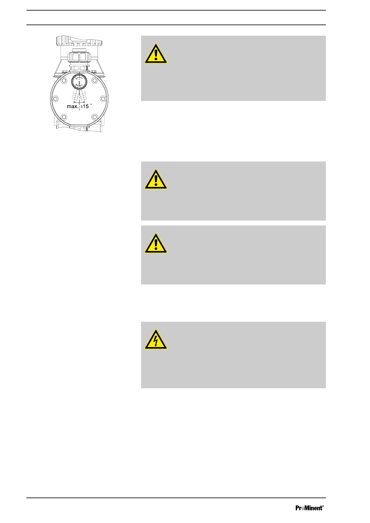
Feed chemical which remains in the overflow line at the
bleeder valve, can attack the valve or cause it to leak
– Route the overflow line with a continuous slope and
moreover with the tube nozzle pointed downwards - see
Fig. 20.
CAUTION!
Danger resulting from unnoticed diaphragm rupture
If the pump has been ordered with an electric diaphragm rup‐
ture sensor, it still has to be installed.
– Screw the enclosed diaphragm rupture sensor into the
liquid end (no seal necessary).
CAUTION!
Warning of unnoticed diaphragm rupture
Only above approximately 2 bar system back pressure is a
signal generated upon a diaphragm rupture.
– Only rely on the diaphragm rupture sensor at back pres‐
sures greater than 2 bar.
7.2
Installation, electrical
WARNING!
Danger of electric shock
Unprofessional installation may lead to electric shocks.
– All cable cores cut to length must be provided with cable
end sleeves.
– The Installation, electrical of the device may only be
undertaken by technically trained personnel.
What requires electrical installation?
n Level switch
n Diaphragm rupture sensor, electrical (option)
n Dosing monitor (option)
n Relay (option)
n External control
n mA output (option)
n Bus connector (option)
n Timer (option)
n Pump, power supply
Fig. 20: Permissible alignment of the
bleeder valve
Diaphragm rupture sensor
General safety notes
What requires electrical installation?
Installation
34