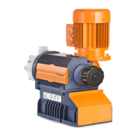
CAUTION!
To check the pressure conditions in the piping system it is
recommended that connecting options are provided for a
manometer close to the suction and pressure connector.
1 Manometer socket
2 Discharge line (pipe)
3 Discharge valve
4 Suction valve
5 Suction line (pipe)
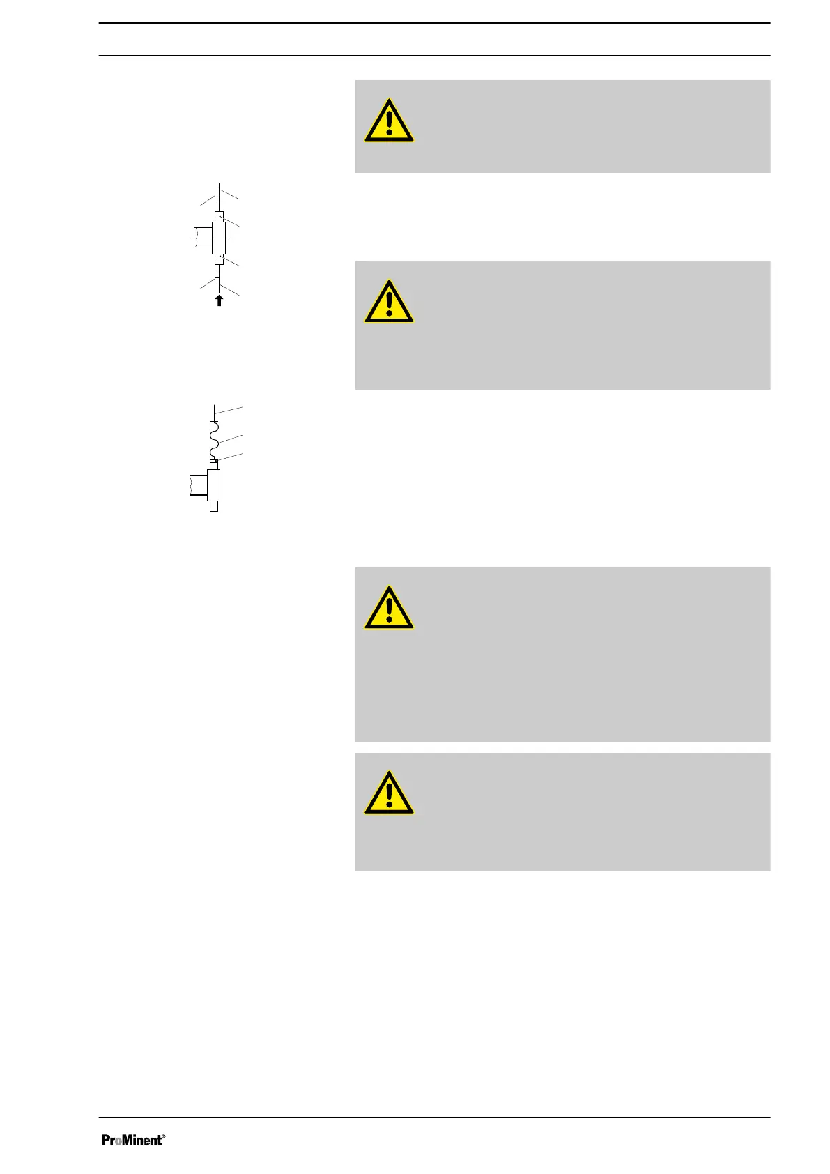
CAUTION!
Connect the pipelines to the pump so that no residual forces
act on the pump, e.g. due to the offsetting, weight or expan‐
sion of the line.
Only connect steel or stainless steel piping via a flexible
piping section to a plastic liquid end.
1 Steel pipeline
2 Flexible pipe section
3 Plastic liquid end
CAUTION!
Warning of feed chemical spraying around
If no overflow line was connected to the integral bleeder
valve, feed chemical sprays out of the tube connection as
soon as the bleeder valve opens.
– An overflow line must always be connected to the inte‐
gral bleeder valve and be fed back to the storage tank or
- if required by the regulations - into a special storage
tank.
CAUTION!
Danger of cracking
Cracking of the PVT liquid end can occur if a metal overflow
line is connected to the bleeder valve.
– Never connect a metal overflow line to the bleeder valve.
Fig. 18: Manometer connecting options
Fig. 19: Steel pipeline at the liquid end
Integral bleeder valve
Installation
33