MVI56E-MCMR ♦ ControlLogix Platform Reference
Modbus Communication Module with Reduced Data Block User Manual
ProSoft Technology, Inc. Page 147 of 223
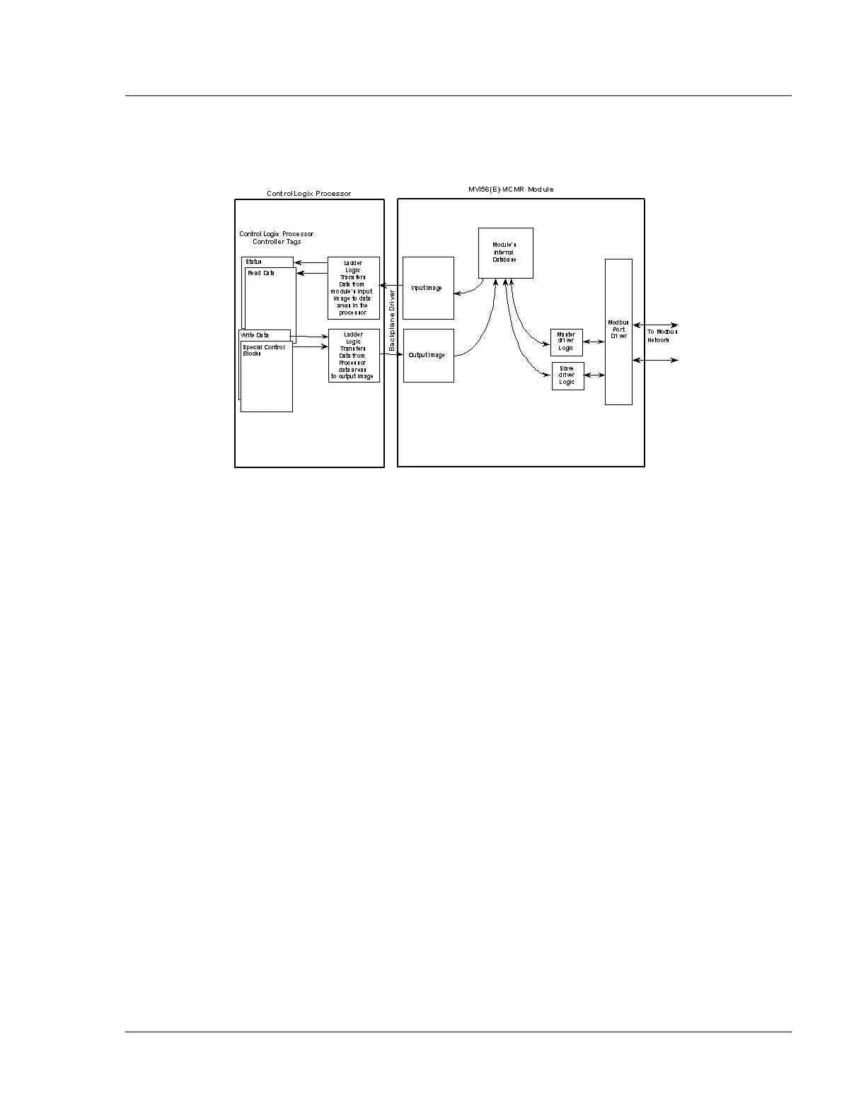
The following illustration shows the data transfer method used to move data
between the ControlLogix processor, the MVI56E-MCMR module, and the serial
network. This applies only for the scheduled I/O data.
As shown in the diagram, all data transferred between the module and the
processor over the backplane is through the Input and Output Images. Ladder
logic must be written in the ControlLogix processor to interface the Input and
Output Image data defined in the controller tags. The user is responsible for
handling and interpreting all data received on the application ports and
transferred to the Input Image.
 Loading...

