Reference MVI56E-MCMR ♦ ControlLogix Platform
User Manual Modbus Communication Module with Reduced Data Block
Page 148 of 223 ProSoft Technology, Inc.
Using Data Blocks
Each block transferred between the module and the processor contains block
identification codes that define the content or function of the block of data
transferred.
Blocks -1 and 0 contain no data when transferred from the processor to the
module. Blocks 1 to 125 transfer data stored or to be stored in the module’s
database 40-words of data per block. These data blocks send data from module
to the processor (monitored data received from the devices on the serial network)
and to send data from the processor to the module (control data to send to the
end devices). Block identification codes 9901 to 9999 are used for special
function blocks to control the module.
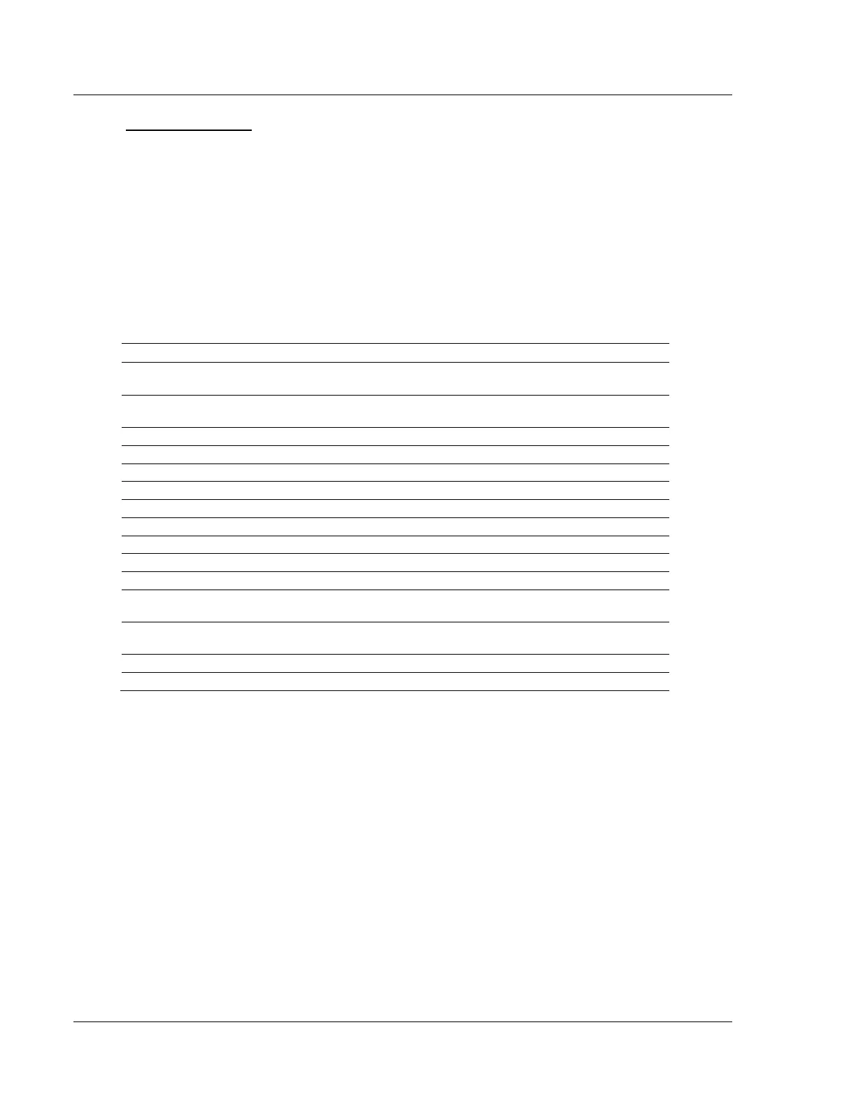
The following table describes the block identification codes used by the module.
Null (Used when Read or Write Register
Count = 0)
Read or Write Data Blocks
Initialize Output Data Blocks
Module Error/Status Data Block
Event Command Block for Port 1
Event Command Block for Port 2
Command Control Block for Port 1
Command Control Block for Port 2
Get Command Error List for Port 1 Block
Get Command Error List for Port 2 Block
Get Slave Enable/Disable Data for Port 1
Block
Get Slave Enable/Disable Data for Port 2
Block
As you can see, some data is transferred between the module and the
ControlLogix processor using the Input and Output Images (Type=I/O), and some
is transferred using MSG blocks (Type=MSG). Data transferred using the Input
and Output Images is used for high-speed, deterministic delivery time data,
controlled by the Requested Packet Interval (RPI) assigned to the module in the
I/O configuration in RSLogix 5000. The MSG data is used for lower priority data
and is transferred using MSG instructions under ladder logic control. MSG data is
handled when there is time available in the unscheduled bandwidth of the
network.