Page 18 of 76
Condensed Operating Instructions (Continued)
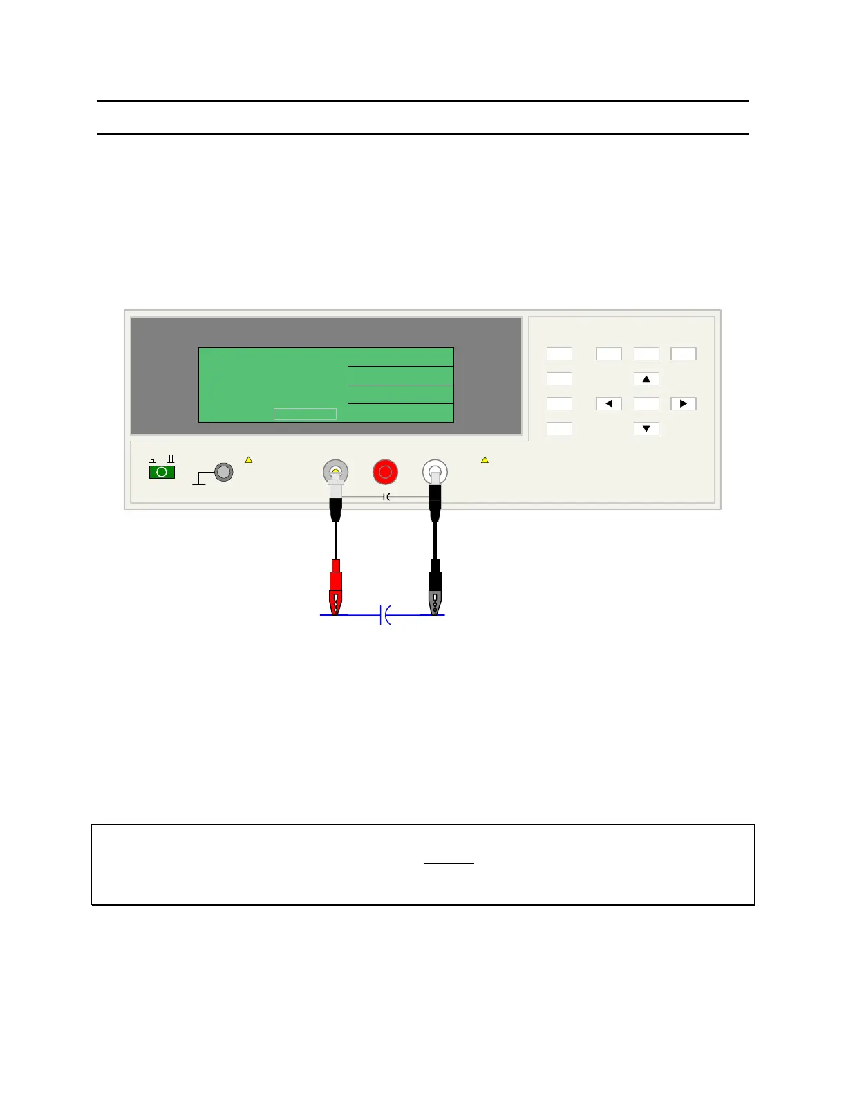
3. Connection to Device under Test (DUT)
Figure COI-3 illustrates the connection of the 1855 instrument to a DUT using the 1855-01 Lead
Set. For Leakage Current, Insulation Resistance and Withstand Voltage Tests, the red alligator
clip/BNC cable is connected between the silver INPUT terminal on the 1855 unit and the high
side of the device under test. The black alligator clip/banana cable is connected between the
white HV (-) terminal on the 1855 unit and the low side of the DUT.
1855 Capacitor Leakage Current /IR Meter
(-)(+)INPUT
QuadTech
+
HV
F1
F4
F3
F2
F1
F3
F2
MEAS
DISPLAY
F4
TRIGGER
MAIN
INDEX
SYSTEM
SETUP
01
l
<MEAS. DISPLAY: SEQ. TEST>
NEXT PAGE 1/2
2
0.5
TEST V
LC :
1.0
C.C
RANGE
1.5 mA
CHARGE/TEST DISCHARGE
CHARGE TEST DISCHARGE
:
:
:
V
mA
uA
-
DUT
A
COI-3: Connection to DUT for LC Test
4. Make a Measurement
1. Press [MEAS DISPLAY]
2. Connect device under test (DUT) to test leads.
3. Press [TRIGGER].
4. Record measurement.
NOTE
Please read this instruction manual in its entirety before operating this instrument.
These condensed operating instructions are not a substitute for all the information provided in the
remainder of this manual.