Instructions for Use RAUMEDIC
MPR2 logO
Manufacturer: zwo-400EN
RAUMEDIC AG, Hermann-Staudinger-Strasse 2, 95233 Helmbrechts, Germany Rev. 9 2020-09-22
Page 46 of 99
4.4.3.2 Connecting the cable to the MPR2
Use the following connection ports on the MPR2:
Port P2/T2 to connect the PTO cable, port [20] in Fig. 2
Port pO
2
to connect the FOC, port [19] in Fig. 2
Port P1 on the MPR2 is not intended for the connection of the PTO cable and of the PTO catheter.
Exclusively use the multi-purpose port P2/T2, if you want to use the PTO cable to connect the
PTO catheter to the MPR2 !
It is imperative that you avoid moisture or fluid getting at the electric plug-in connectors of the
PTO catheter, the PTO cable and the ports P2/T2.
Avoid any scratching and any soiling of the photo-optical plug-in connectors of the catheter, the
FOC and the pO
2
port.
When all cable connections between the PTO catheter and the MPR2 have been established, the MPR2
has been switched on, the sensors have been attached to the patient, the memory mode has been defined
and the limiting alarm values have been selected, the measurement is started immediately when this setting
mode is left. There is no query for the measuring location of the invasive pressure, neither will the catheter
zeroing function be carried out (cf. chapter 3.1.2.3 Zero calibration
). All necessary information has been
saved to the catheter (EEPROM in the catheter connector), which is read out automatically when the MPR2
is connected. The system automatically allocates the ICP2 measuring location so that the zeroing of the
RAUMEDIC catheter is correct.
4.4.3.3 Setting the partial oxygen pressure
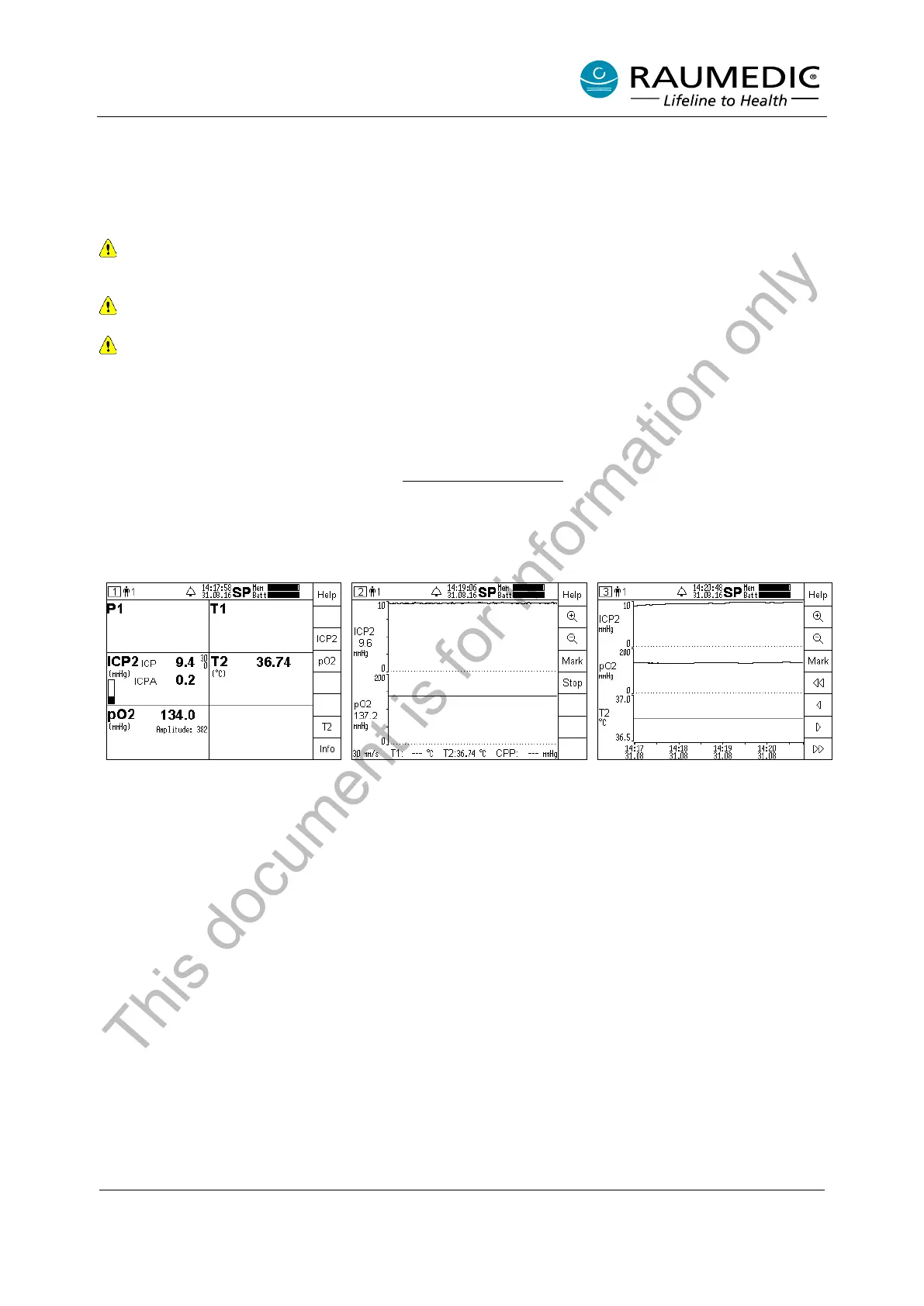
Step 1:
The pO2 is displayed in screen 1
(overview) as well as the limiting
alarm values, if and when
necessary, if this function has
been activated. The amplitude
value renders the technical
information on the signal quality. If
the pO2 key is pressed, other
settings can be carried out.
Step 2:
In screen 2 (curves) the pO2 is
represented graphically. The other
setting options by means of the
soft keys correspond to those of
the invasive pressure.
Step 3:
Screen 3 (trend) renders the pO2
as a trend. The other setting
options by means of the soft keys
correspond to those of the
invasive pressure.
This document is for information only