Instructions for Use RAUMEDIC
MPR2 logO
Manufacturer: zwo-400EN
RAUMEDIC AG, Hermann-Staudinger-Strasse 2, 95233 Helmbrechts, Germany Rev. 9 2020-09-22
Page 75 of 99
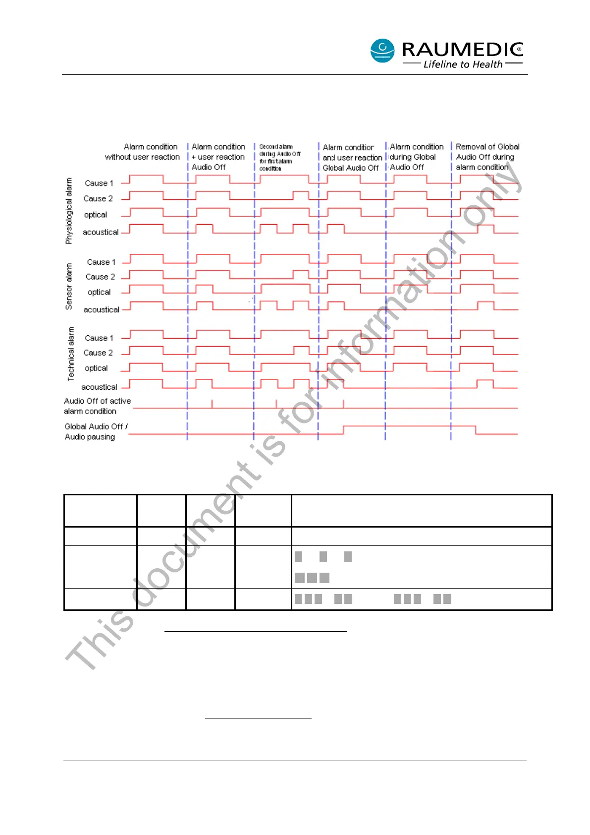
4.9.5 Summarisation
The following diagram renders clear the relationships between the cause of the alarm, the alarm signals
and the AUDIO OFF for the active alarm conditions (short key depression) as well as global AUDIO OFF /
global AUDIO PAUSING (long key depression).
Figure 10: Alarm diagram
The following table indicates how the different alarms are acoustically and optically noticed by the operator.
Alarm
condition
LED [6]
*1
LED [7]
*1
Display
Sound
none green off normal none
*2
off yellow
approx. 30 sec. break
*3
off yellow
approx. 20 sec. break
high priority red red
approx. 6 sec. break
Table 7: Alarm conditions
*1: Cf. Table 1 in chapter 2.5 Operating elements, connections, displays
*2: Individual actions are indicated by individual short sounds.
*3: Physiological and technical alarm
4.9.6 Verifying the alarm system
The alarm system can be verified at any time. When checking the acoustic signal, please observe that you
do not switch off the acoustic alarm permanently with the AUDIO OFF key. To verify the alarm system,
proceed as described in chapter 4.6.2 Device diagnostics
. Please observe when verifying the alarm system
that alarms of high and medium priority are tested according to the table rendered above.
This document is for information only