Instructions for Use RAUMEDIC
MPR2 logO
Manufacturer: zwo-400EN
RAUMEDIC AG, Hermann-Staudinger-Strasse 2, 95233 Helmbrechts, Germany Rev. 9 2020-09-22
Page 58 of 99
4.5 Configuring the graphics display
Screen as well as screen renders graphical displays of the measured or calculated parameters;
screen renders live data, and screen provides the trend. If several transducers have been
connected, the display area is divided up into several tracks. Thus, an overview of all connected parameters
is obtained. At the same time, however, the amplitude resolution decreases with the increase in the number
of tracks. Sometimes, however, it is necessary to have certain or individual parameters in a higher
resolution amplitude. In screen as well as in screen it is possible to deselect tracks in the graphics
display after having pressed the Shift key of the connected (e.g. ICP, ART) or calculated signals (CPP),
which increases the resolution of the remaining tracks; in addition, tracks can be added, which decreases
the resolution of the tracks.
The key function is alternating for the deselection of the tracks. Available parameters for the
function keys are displayed. The graphics track can be deselected by pressing the key, which
will be added again when the key is pressed again.
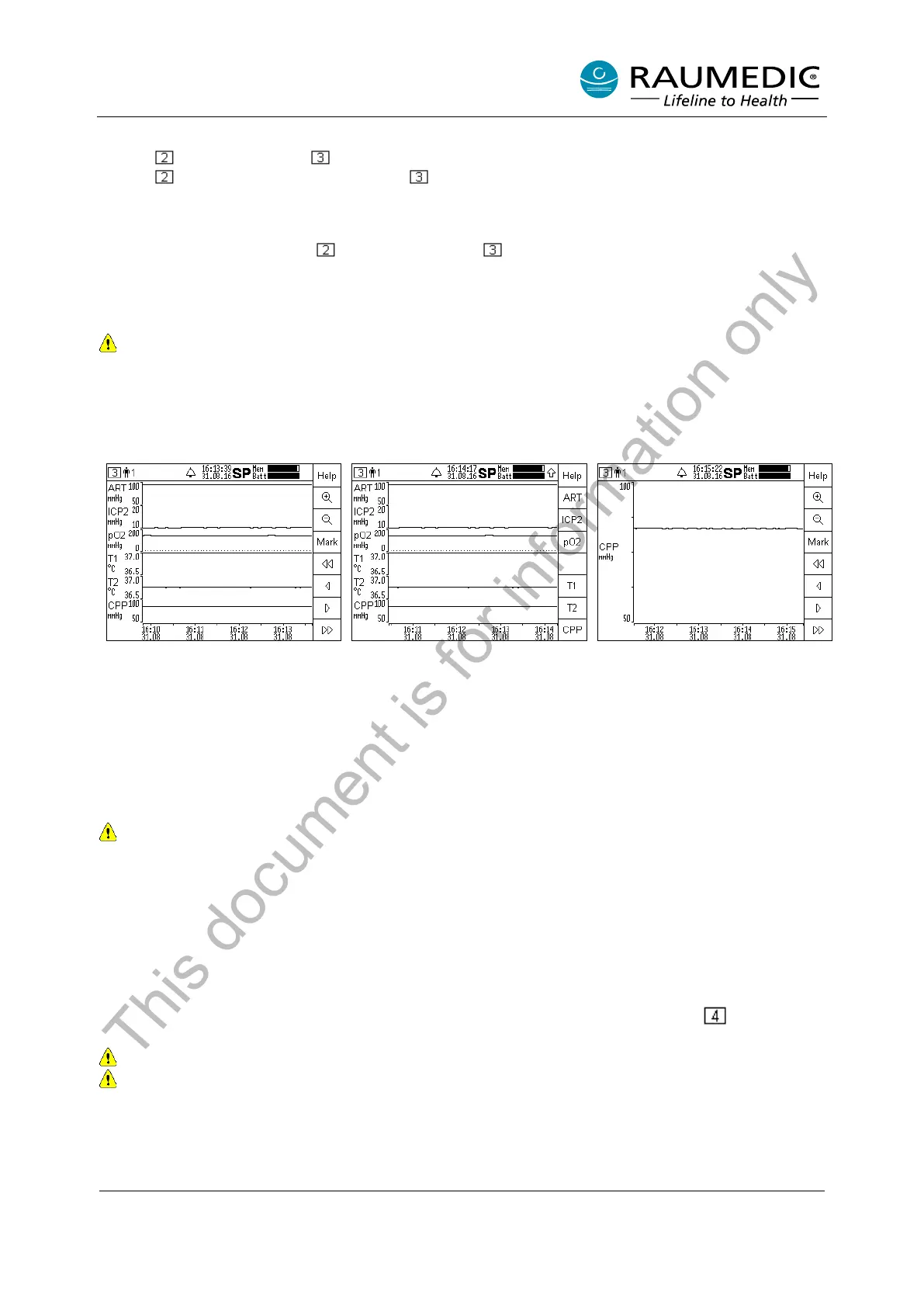
From the following example, you can see which operating steps are required to configure the graphical
representation.
Step 1: Press the Shift key, and
thus change the allocation of the F
keys; the parameters available for
the F keys are displayed.
Step 2: Select the F key
parameters which you want to
select or deselect as graphics
tracks. For example, press the F
keys ART, ICP1 and ICP2 to
deselect these graphics tracks and
to display the CPP at maximum
resolution.
Step 3: Either you press the Shift
key again to return to scroll mode
(as in step 1) or it is set
automatically
seconds.
Tracks can be deselected until no curve is visible any more. In this case, the display will render
“Use Shift + ‘channel name’ to display curves”. The procedure in screen 2 and 3 is identical.
4.6 Device setup
4.6.1 Combine analogue outputs
4.6.1.1 Forwarding an individual pressure signal to Out1 or Out2
The MPR2 has two identical analogue outputs to transfer up to two invasively measured pressure signals
to a third-party system (bed-side monitor) with alarm function. The software of the MPR2 provides two
options to connect the analogue outputs to a third-party system. One option has already been described in
chapter 4.4.2.3 Combine analogue outputs. Another option is rendered in set-up screen .
Pay attention, only the pressure channels ICP1, ICP2 and pO2 can be transferred.
Use approved accessories only.
In order to be able to use the analogue outputs with a third-party system, the following operating steps have
to be carried out:
• Establish the cable connection between Out-1 or Out-2 of the MPR2 and pressure measurement
input of the third-party system.
This document is for information only