CHAPTER 3
26 Viper Pro Installation & Operation Manual
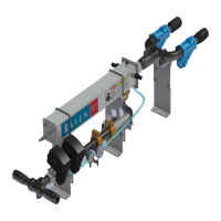
MOUNT THE ULTRAGLIDE XT VALVE ASSEMBLY
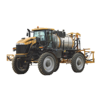
FIGURE 5. Valve Mounting Location
1. Locate the UltraGlide XT valve mounting location on the boom tree assembly, to the right of the machine’s
hydraulic valve.
2. Secure the UltraGlide XT valve (P/N 063-0131-154) to the mounting bracket (P/N 107-0172-179) using two 5/16”-
18 UNC x 4” bolts (P/N 311-0052-092) and two 5/16” - 18 nylon-insert lock nuts (P/N 312-4000-059).
3. Mount the UltraGlide XT valve mounting bracket on the boom tree assembly using two 2-9/16” W x 3-1/2” L x
3/8” thread U-bolts (P/N 107-0171-616) and four 3/8”-16 flanged lock nuts (P/N 312-1001-164).
Fitting Part Number Port
Fitting - -4 SAE O-Ring Plug 333-0012-051
GT, GP, G1,
G2, LS, LS1, GLT,
GRT
Fitting - -6 SAE O-Ring Plug 333-0012-104 P1, T2
Fitting - -6 ORFS (M) to -6 SAE O-Ring (M) Straight Adapter 333-0012-084 P2, T1
Fitting - -6 JIC (M) to -6 SAE O-Ring (M) Straight Adapter 333-0012-045 1, 2
 Loading...


