CHAPTER 4
42 Viper Pro Installation & Operation Manual
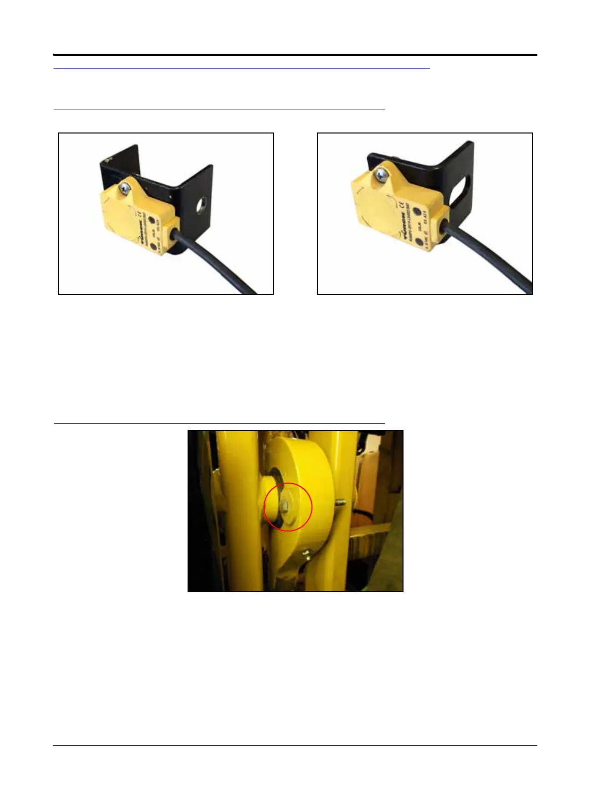
INSTALL THE ROTARY SENSOR
FIGURE 8. Rotary Sensor Installed on Mounting Bracket
1. Determine the correct rotary sensor bracket for your machine.
• 2009 RoGator - P/N 107-0172-177
• 2010-2011 RoGator - P/N 107-0172-177 or P/N 107-0172-268
• 2012 and Newer RoGator - P/N 107-0172-268
2. Install the non-contact rotary sensor (P/N 063-0181-018) on the rotary sensor bracket using two #8-32 x
1/2” screws (P/N 311-0001-013) and two #8-32 hex nuts (P/N 312-1001-020).
FIGURE 9. Pivot Bearing Bolt to be Removed
3. Remove the horizontal bolt at the rear of the pivot bearing.
NOTE: The existing washers will be used later in the installation procedure. The original bolt and hex nut will
not be reused in the UltraGlide XT installation.
Sensor Installed on Bracket P/N 107-0172-268Sensor Installed on Bracket P/N 107-0172-177
 Loading...

