CHAPTER
4
Manual No. 016-0171-122 Rev. E 37
CHAPTER 4
SENSOR INSTALLATION
NOTE: If the AutoBoom UltraGlide kit is already installed on the machine, it may or may not be necessary to
install additional boom sensors. If boom sensors are being installed on the machine, complete all
sections in this chapter. If no boom sensors are being installed, proceed to the Install the Rotary
Sensor section on page 42.
BOOM SENSOR MOUNTING LOCATIONS
Sensor mounting locations may be influenced by the boom configuration. If an object enters the sensor’s blind
range unexpectedly, a false echo return to the sensor could occur, causing the boom to drop and the sensor or
boom to be damaged. To ensure optimal operation of the UltraGlide XT system and to protect the sprayer boom,
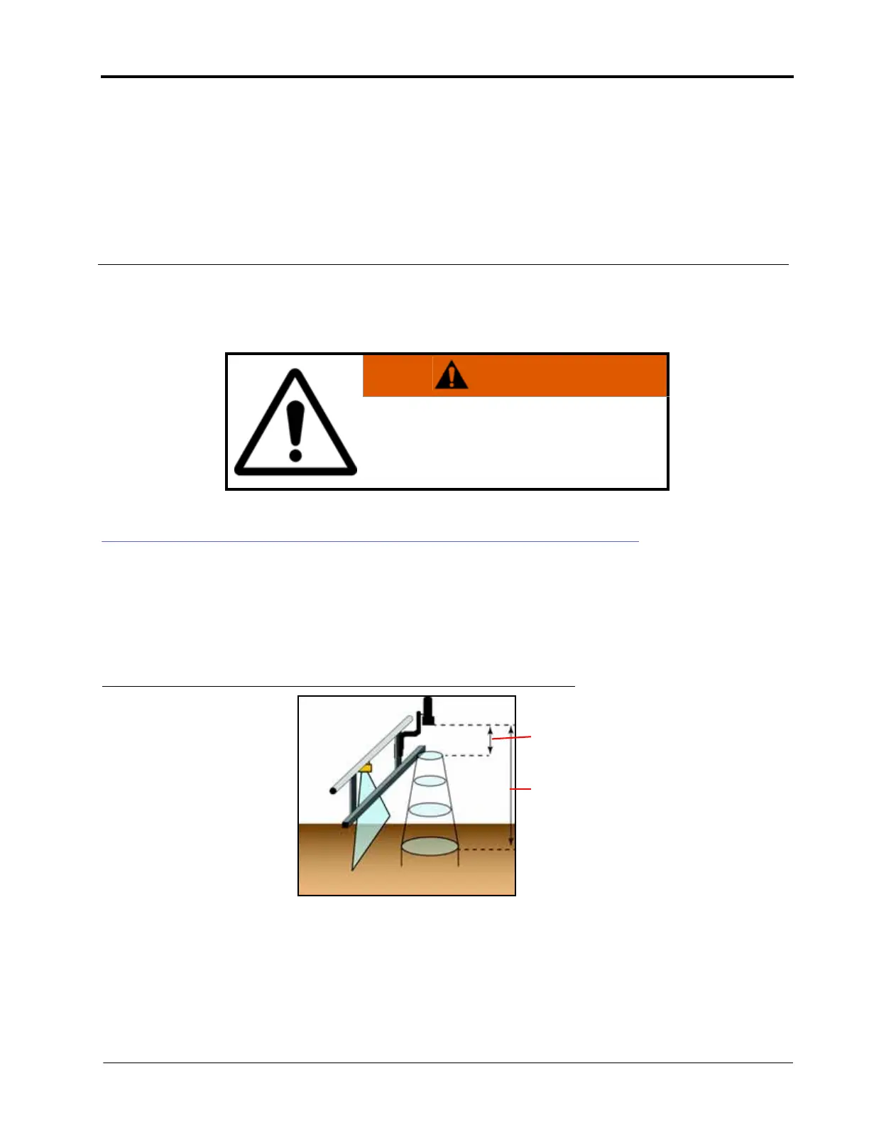
the sensor should be mounted on the front side of the boom, 8 - 10” above the lowest hanging part of the boom.
FIGURE 1. Illustration of Sensor’s Blind Range
WARNING
The machine must remain stationary and
switched off, with the booms unfolded and
supported, during installation or maintenance.
1/2 Sensor to Target
Distance
Sensor Blind Range
8”
Sensor to Target
Distance
 Loading...

