5
Manual No. 016-0171-122 Rev. E 47
WIRING INSTALLATION
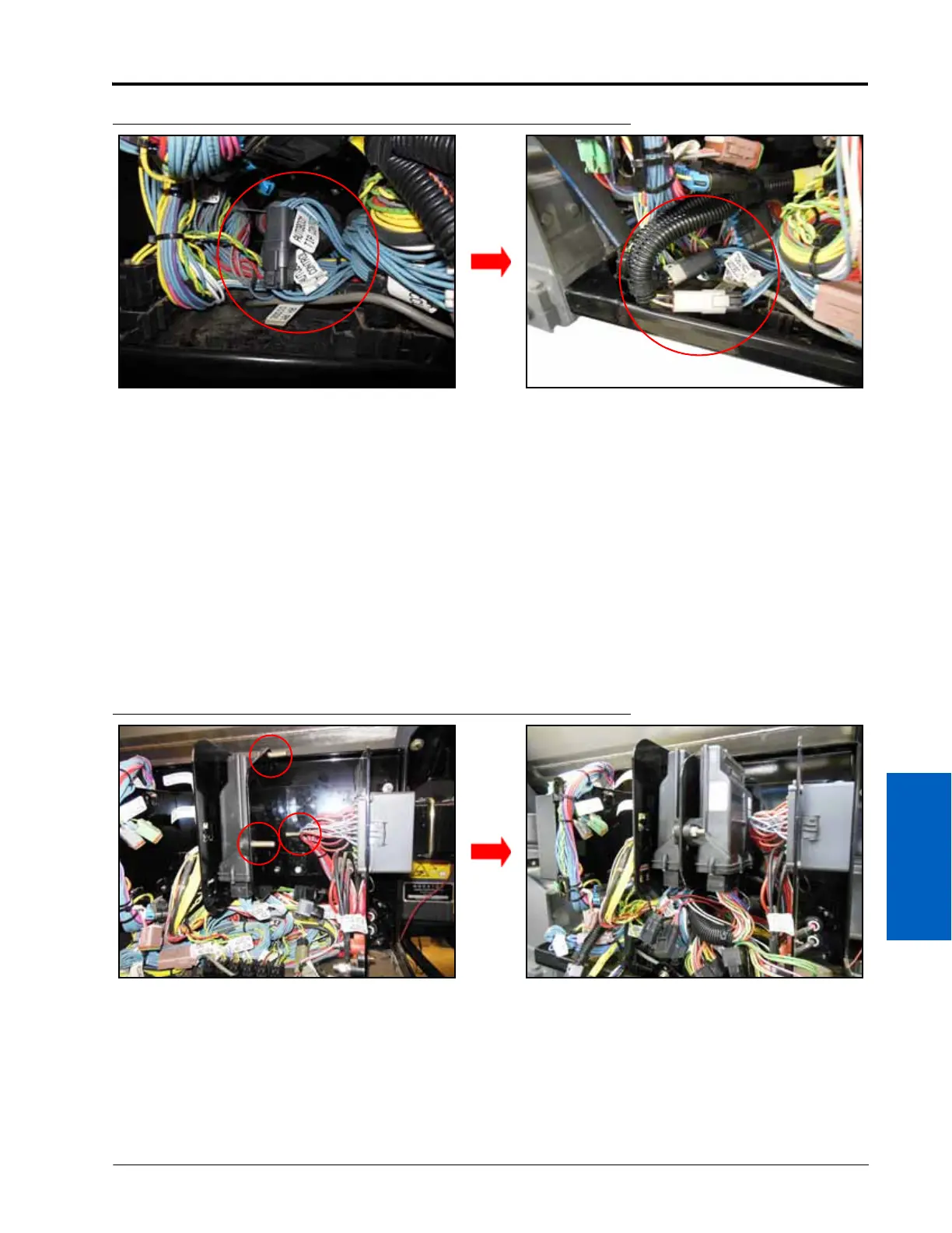
FIGURE 4. Existing AutoBoom Tip Control Connection
9. Locate and disconnect the existing AUTOBOOM TIP CONTROL connections.
IMPORTANT: There are two sets of AUTOBOOM TIP CONTROL connections. Use the connectors that are connected
together, not the connectors that are capped off.
10. Connect the AUTOBOOM TIP CONTROL connectors to the mating BOOM SENSE 1 and BOOM SENSE 2
connectors of the node harness.
11. Insert the large, rectangular node connectors from the node harness into the correct ports of the UltraGlide XT
node (P/N 063-0130-023 or 063-0130-024).
12. Connect the ground leads to the negative battery terminal located near the front of the node mounting box.
13. Connect the power leads to the positive battery terminal.
INSTALL THE ULTRAGLIDE XT NODE
FIGURE 5. UltraGlide XT Node Installed
1. Mount the UltraGlide XT node (P/N 063-0130-023 or 063-0130-024) on the existing node mounting bracket
(mounting hardware not provided).
NOTE: If a node mounting bracket is not present, contact your AGCO dealer for ordering information.
2. Tighten the nuts to ensure the node is mounted securely.
 Loading...

