3
Manual No. 016-0171-122 Rev. E 29
HYDRAULIC SYSTEM INSTALLATION
3. Connect the machine’s tank hose to the opposite end of the installed tee fitting.
4. Install the -8 ORFS end of the supplied hydraulic hose (P/N 214-1001-092) on the 90° end of the installed tee
fitting.
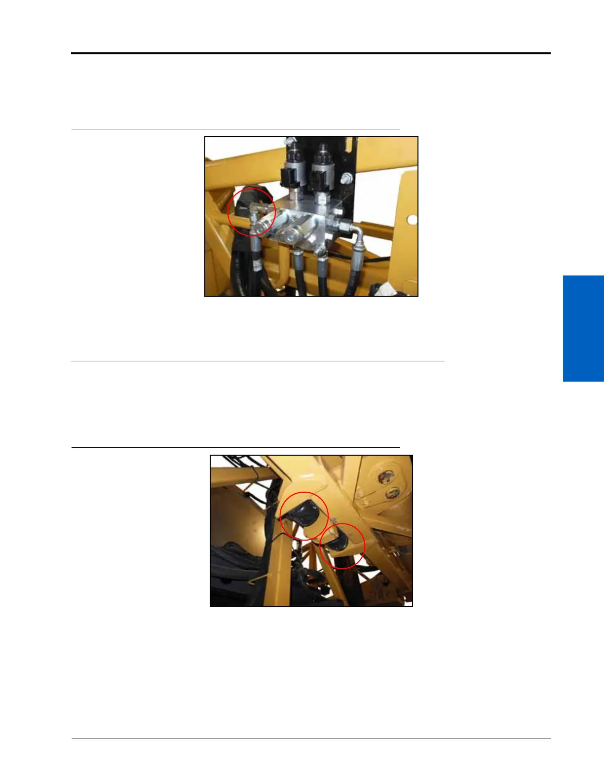
FIGURE 11. Tank Hose Installed on UltraGlide XT Valve
5. Connect the -6 FF end of the installed hydraulic hose to port T1 of the UltraGlide XT valve.
INSTALL THE ULTRAGLIDE XT CYLINDERS
1. Unfold the booms and lower the center rack to its lowest position.
2. Machines With 120’ Booms or Heavy Duty Center Rack Only - Locate and remove the rubber bumpers on the
bottom front of the machine’s center rack.
FIGURE 12. Rubber Bumpers
3. Remove the left factory-installed shock absorber.
 Loading...

