5
Manual No. 016-0171-122 Rev. E 51
WIRING INSTALLATION
FIGURE 11. AUTOBOOM TIP CONTROL Connectors
3. Locate and disconnect the machine’s AUTOBOOM TIP CONTROL connectors.
4. Plug the AUTOBOOM TIP CONTROL connectors into the mating BOOM SENSE 1 and BOOM SENSE 2
connectors on the node harness cable (P/N 115-0230-104).
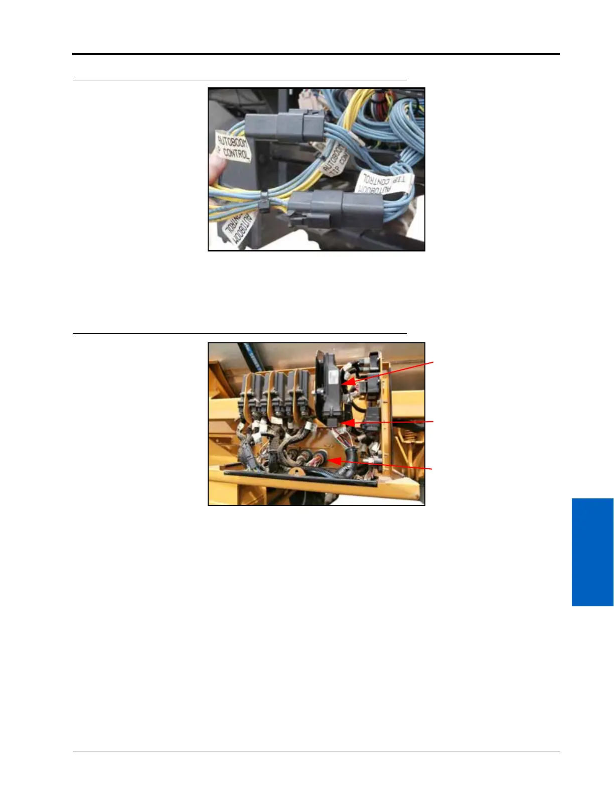
FIGURE 12. AutoBoom Node Installed
5. Connect the large, rectangular connectors on the node harness into the correct ports of the AutoBoom node
(P/N 063-0130-023).
6. Tighten the bolts on the node connectors to secure the connections.
7. Secure the AutoBoom node to the node mounting bracket (P/N 107-0171-348) using three 3/8”-16 x 1-1/4” hex
bolts (P/N 311-0054-081) and three 3/8”-16 nylon insert lock nuts (P/N 312-4000-061).
8. Mount the node mounting plate to the node mounting box using the supplied 1/4”-20 x 3/4” self-tapping
screw (P/N 311-0001-345).
9. Install the 31-pin connector on the node harness through the inboard side of the node box, securing it using
the bulkhead washer and lock nut that were removed from the bulkhead plug.
INSTALL THE VALVE HARNESS
NOTE: The instructions in this section assume that you are standing behind the machine, looking toward the
cab.
AutoBoom Node (P/N
063-0130-023)
Node Connectors
on AutoBoom
Harness
31-Pin Bulkhead
Connector on
AutoBoom Harness
 Loading...

