CHAPTER 5
54 Viper Pro Installation & Operation Manual
MODEL YEAR 2009 NODE AND HARNESS INSTALLATION
INSTALL THE ULTRAGLIDE XT NODE
FIGURE 16. Installed AutoBoom Node
1. Mount the AutoBoom node (P/N 063-0130-023) on the mounting bracket (P/N 107-0171-619) using three
3/8”-16 UNC x 1-1/4” hex bolts (P/N 311-0054-106) and three 3/8”-16 zinc flanged lock nuts (P/N 312-1001-164).
2. Secure the mounting bracket to the machine’s center rack using two 2-9/16” W x 3-1/2” L x 3/8” thread U-bolts
(P/N 107-0171-616) and four 3/8”-16 zinc flanged lock nuts (P/N 312-1001-164).
NOTE: Position the node so that the cable connectors face down or to the side. One of the six numbered
direction arrows on the node must be oriented in the direction of vehicle travel, one arrow pointing
straight up, and two arrows parallel to the ground.
3. Insert the large, rectangular node connectors on the harness cable (P/N 115-0230-095 or 115-0230-116) into the
correct ports of the AutoBoom node.
4. Tighten the bolt on the node connectors to secure the connections.
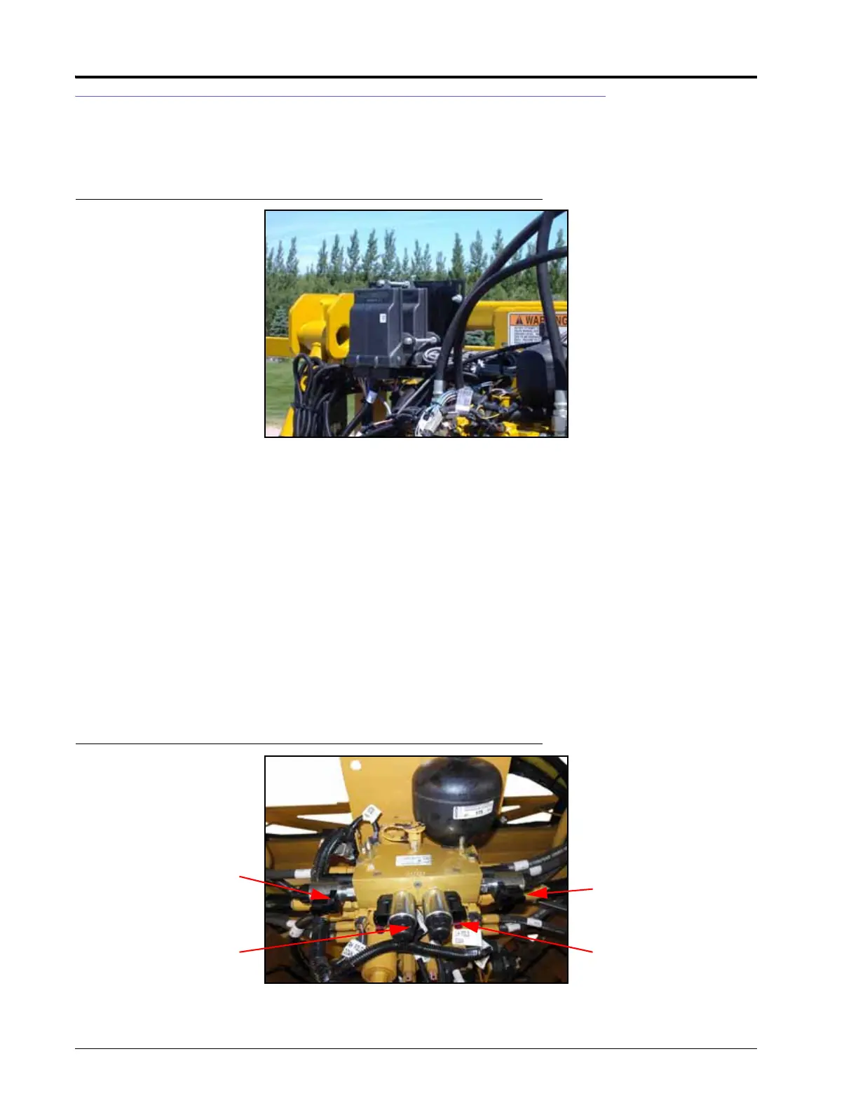
CONNECT THE HARNESS TO THE BOOM FUNCTION CONTROLS
FIGURE 17. Harness Cabling Connections
1. Locate the LEFT PRESS and RIGHT PRESS connectors on the valve harness (P/N 115-0230-095 or 115-0230-116).
Left Prop
Left Solenoid
Right Prop Port
Right Solenoid
 Loading...

