5
Manual No. 016-0171-122 Rev. E 53
WIRING INSTALLATION
FIGURE 14. Existing CAN Terminator
4. Connect the CAN BUS connector on the AutoBoom power/CAN cable to the open connector on the machine’s
harness.
5. Install the terminator on the TERMINATOR connection of the AutoBoom power/CAN cable.
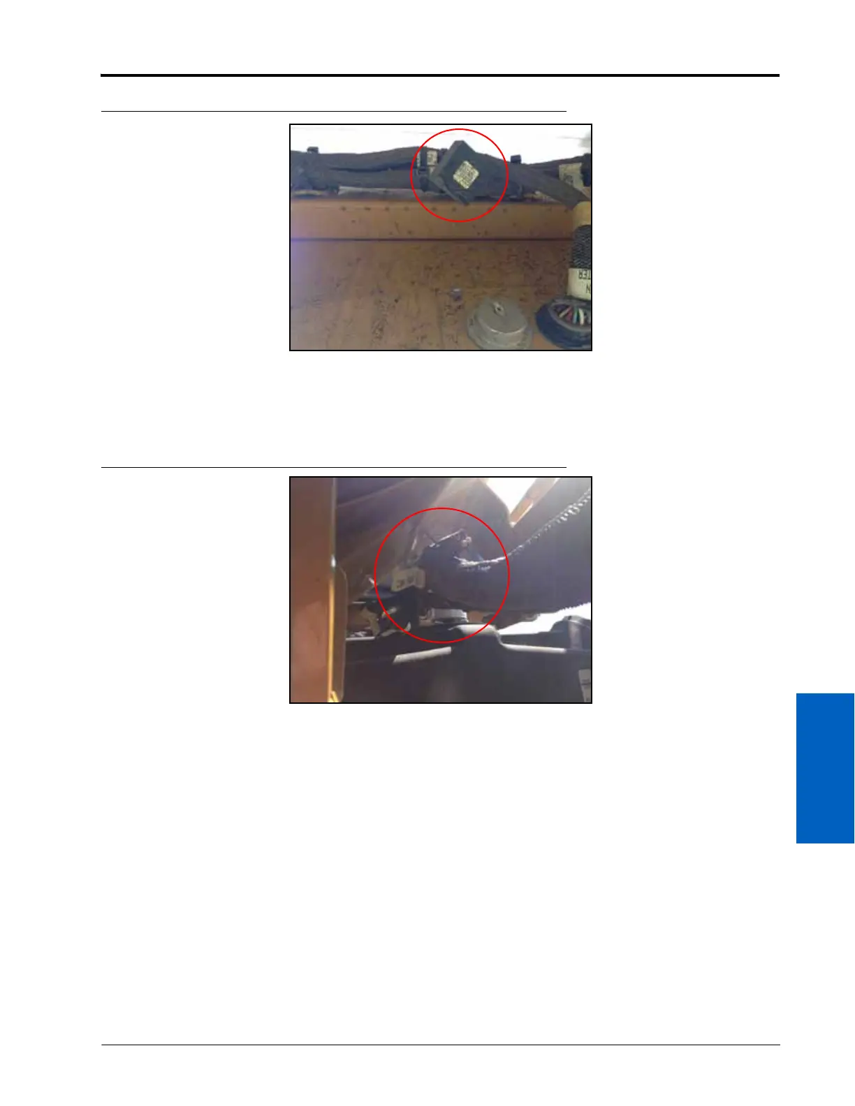
FIGURE 15. CAN PWR Connector
6. Locate the machine’s CAN PWR connection outside of the node box.
7. Remove the cap from the CAN PWR connection.
8. Connect the SW PWR connector of the AutoBoom power/CAN cable to the machine’s CAN PWR connector.
9. Route the remaining AutoBoom power/CAN cable along the machine’s existing cabling and toward the battery
box at the front of the machine.
10. Install the high current power and ground wires on the power cable to the power and ground studs located in
the machine’s battery box.
 Loading...

