3
Manual No. 016-0171-122 Rev. E 31
HYDRAULIC SYSTEM INSTALLATION
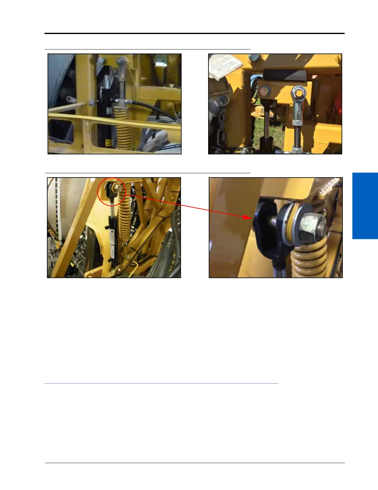
FIGURE 15. Cylinder Installed - 90’-100’ Booms
FIGURE 16. Cylinder Installed - 120’ Booms
6. Insert a 3/4”-10 UNC x 4” bolt (P/N 331-0062-160) through the clevis and the cylinder end.
7. Install a 3/4” flat washer (P/N 313-2300-023) on the end of the installed bolt.
8. Secure the cylinder in place using a 3/4”-10 nylon insert lock nut (P/N 312-4000-071).
9. Position the base-end of the hydraulic cylinder in the machine’s bottom mounting clevis.
10. Repeat steps 5-8 above to secure the base of the hydraulic cylinder.
11. Unfold the left boom tip and fold in the right boom tip to access the shock absorber bolts on the right side.
12. Repeat steps 4-10 above to install the right hydraulic cylinder.
13. Machines with 120’ Booms or Heavy Duty Center Rack Only - Reinstall the rubber bumpers.
INSTALL THE CYLINDER HOSES
1. Install -6 JIC M/M/F swivel run tee adapter fittings (P/N 333-0012-043) in the open ports on the left hydraulic
cylinder (P/N 334-0004-006).
 Loading...

