CHAPTER 3
30 Viper Pro Installation & Operation Manual
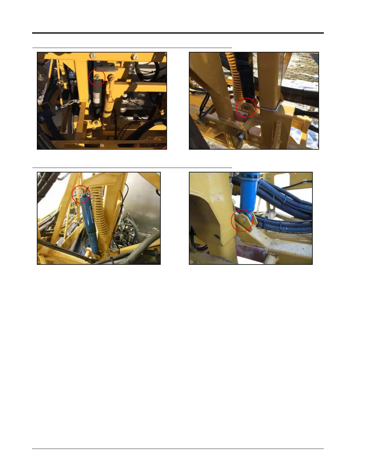
FIGURE 13. Shock Absorber Bolts to be Removed - 90’-100’ Booms
FIGURE 14. Shock Absorber Bolt to be Removed - 120’ Booms
NOTE: On machines with 120’ booms or heavy duty center racks, the lower shock absorber bolts are
accessible only when the center rack is rotated to its extremes. To rotate the center rack, unfold the
outer tip of the right boom while leaving the outer tip of the left boom folded in.
IMPORTANT: To prevent injury, use extreme caution when removing lower shock absorber bolts as shown in the figure
below. The location of these bolts can create pinch points!
4. Position the rod-end of the supplied hydraulic cylinder (P/N 334-0004-006) in the machine’s top mounting
clevis.
5. Insert a 3/4” flat washer (P/N 313-2300-023) between the cylinder and the mounting clevis.
 Loading...

